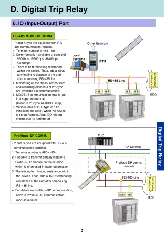
RS-485
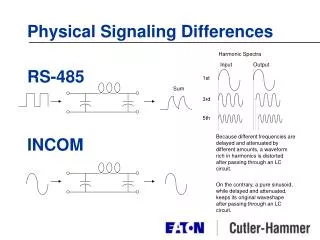
Harmonic Spectra. Input. Output. 1st. Sum. 3rd. 5th. RS-485. INCOM. Because different frequencies are delayed and attenuated by different amounts, a waveform rich in harmonics is distorted after passing through an LC circuit.

RS-485
E N D
Presentation Transcript
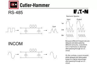
Harmonic Spectra Input Output 1st Sum 3rd 5th RS-485 INCOM Because different frequencies are delayed and attenuated by different amounts, a waveform rich in harmonics is distorted after passing through an LC circuit. On the contrary, a pure sinusoid, while delayed and attenuated, keeps its original waveshape after passing through an LC circuit.
11 00 11 01 0? 1? Detecting RS-485 1’s and 0’s Receivers than convert serial bit streams into parallel data are called UARTs (Universal Asynchronous Receiver Transmitters). A UART determines whether the serial stream contains a 1 or a 0 by sampling at the bit rate (9600, 19.2 k, etc.) For better error immunity it typically samples 2 or 3 times per bit. Two bit readings in a row must be the same for the UART to declare a 1 or a 0. With distorted wave shapes, the UART will typically be observing a data stream where the bit value changes from within a bit time. This can cause the UART to declare various errors (such as framing or parity) and discard the byte.
0 1 0 1 INCOM Decoding Since the waveshape is not changed, it is still easy to detect the difference between a 1 and 0 from an Frequency Shift Keyed (FSK) signal. INCOM signals are not as affected by impedance mismatches (taps, T’s, Y’s, etc.). Consequently the cabling rules are more relaxed than with RS-485.
S1 + S2 S2 Delay S1 + S2 S1 S1 + S2 S2 Delay S1 + S2 S1 Noise Immunity RS-485 Since RS-485 decides if a signal is a 1 or a 0 by examining the amplitude, external events can mask the true value. INCOM INCOM FSK uses a bandpass filter to eliminate signals substantially above or below 100 kHz. Therefore large amplitude interfering signals removed
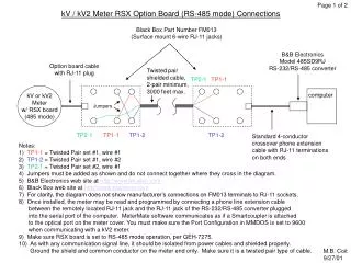
A B C D E F G H I J 1 1 Cutler-Hammer IMPCABLE or Belden 9463 (or equivalent in Plenum) RJ-11 Install in PC CONI This design places brings all network (Lighting Control and Power Monitoring) back to the Central Plant. RJ-45 IN 1 IP 2 Shield 3 Phoenix Contact RJ-11 to Terminals Ethernet Hub Ethernet 10BASE-T RS-232 2 Belden 9207 (or equivalent in Plenum) 2 RS-485/ 232 200’ max Typical Switchboard Tap RS-485 Device To PDS PONI PONI 130 131 3 3 IED IED IED Typical Typical IQ Analyzer IQ Analyzer 4 4 PONI 131 5 5 These taps are legal with INCOM wiring. These are not legal with RS-485 IED RS-485 Network INCOM Network Typical IQ Analyzer 6 6 Parking Garage Parking Lot Terminal RS-485 Network 7 DFTR DATE THE INFORMATION ON THIS DRAWING IS THE PROPERTY OFEATON CORPORATION. IT IS DISCLOSED IN CONFIDENCEAND IS NOT TO BE REPRODUCED, USED OR DISCLOSEDEXCEPT FOR THE PURPOSE FOR WHICH FURNISHED. 1 APPD DATE DGL 11-DEC-98 CUTLER-HAMMER APPD DATE POWER MANAGEMENT PRODUCTS CENTER ENG. REF. DATE TITLE REVISION NEXT REF. DATE 8 SHEET NO 1 OF 1 SIZE SCALE DIRECTORY DWG NO NONE A A B C D E F
RS-485 and INCOMWiring Rules 200feet 200feet 200feet 200feet Total Cable Length to = 13 x 200’ = 2600 feet Conduit space required = sufficient for 2 twisted pairs 200 feet 200 feet 200 feet 200 feet RS-485 Node RS-485 Node RS-485 Node RS-485 Node RS-485 Node 200feet 200feet 200feet 200feet Total Cable Length to = 9 x 200’ = 1800 feet (70% of the RS-485 system) Conduit space required = sufficient for 1 twisted pairs 200 feet 200 feet 200 feet 200 feet IQ Node IQ Node IQ Node IQ Node IQ Node