Download
1 / 14
160 likes | 357 Views
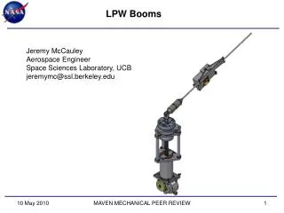
RBSP EFW Spin Plane Booms. Greg Dalton Space Sciences Laboratory University of California, Berkeley. SPB Overview. COMPOSITE CABLE. PREAMPLIFIER ENCLOSURE. SENSOR SPHERE. RELEASE MECHANISM. FINE WIRE. METERING WHEEL. OVER TENSION. HARNESS CONNECTORS. SPOOL. ENABLE PLUG.

E N D
RBSP EFWSpin Plane Booms Greg Dalton Space Sciences Laboratory University of California, Berkeley
SPB Overview COMPOSITE CABLE PREAMPLIFIER ENCLOSURE SENSOR SPHERE RELEASE MECHANISM FINE WIRE METERING WHEEL OVER TENSION HARNESS CONNECTORS SPOOL ENABLE PLUG
SPB Status F1 & F2 SPB’s ready for cable integration
Facilities and MGSE • High Bay deployment for self-shock and length calibration • Door opening self-shock test • Verify proper opening of doors, IDPU indication • Monitor current and voltages of motor, pin puller • Length Calibration, meter wheel turns counter High Bay flying pulley MGSE Functional deploy MGSE
Facilities and MGSE • Vibration Facility – Quanta Laboratories, Santa Clara • Readily available for testing • Force limiting test performed on ETU • One instrument per day • Vibration per EDTRD: • Vibe fixtures for RBSP S/C mounting – force limiting • Unpowered Testing • ETU to qualification levels, flight to protoflightlevels • Test sequence on all three axis: • Fixture only all tests • ¼ G sweep to verify 1st mode • ½ G @ 40 Hz to validate controller and force gages • Random • ¼ G Sweep • 5-100 Hz Sine Strength • ¼ G Post Sweep
Facilities and MGSE • Thermal Vacuum Chamber – SSL • Chamber used on for THEMIS SPB deployments • Mechanical GSE ready for TVAC deployment • Chamber prepared for testing
Facilities and MGSE Deployment Sequence (video)
TVAC Profile • One full survival cycle • 3 operational temperature cycles • Hot deploy • Cold Deploy • Six cycles total • CPT to verify electronics functionality
ECN Summary • ECN-006 • ECN closed out • New Parts made, added to Cable Fabrication assembly • Description:
RFA Summary • EFW-CDR-10/11 • RFA from CDR closed out • Analysis was completed and report delivered • Description: • EFW-CDR-10 • Action: Verify deployment ring spring stress margin (update stress table on chart 466) Increasing spring tension lowers stress margin. • Rationale: Deployment ring uses two springs in tension to help actuate the restraint mechanism. • EFW-CDR-11 • Action: Verify deployment spring force margin at worst case condition • Rationale: Deployment ring uses two springs in tension to help actuate the restraint mechanism.
PFR Summary • PFR-006 • PFR dated 4/7/10 closed out • PFR report submitted and accepted • Description: • While removing SPB Preamplifier PWB Assembly #16 from the Preamplifier TVAC MGSE, the Ferrule Spring caught on the technicians glove and was pulled from the Preamplifier Enclosure. The technician bobbled the PWB Assembly, which then rolled down the technician's smock, along the technician's pant leg to his shoe, then free-fell a distance of 6 inches to the floor. • Corrective Action/Resolution: • The SPB #16 Preamplifier PWB Assembly was inspected under a microscope by SSL QA. It was then electrically bench tested satisfactorily, then satisfactorily completed a thermal vacuum electrical test.The corrective action is to take care when handling Preamplifier PWB Assemblies, ensuring the preamplifier is assembled/disassembled near a surface and removes the possibility of dropping. The technician shall use a pair of tweezers to remove the Preamplifier PWB Assembly and maintain positive control. This will minimize the risk of the Ferrule Spring from catching on gloves, ESD jacket sleeve, or other GSE.
SPB Status • Instrument Status • F1 instruments are completely built, CPT complete, initial High Bay deployment (self-shock) and length calibration complete • F2 instruments at built at sub-component level • Flight Spares (2) are built at sub-component level • All instruments built to print per RBSP-EFW-SPB-003 Indentured Drawing List Revision C • Documentation • Travelers complied • No outstanding ECN’s, RFA’s, or PFR’s • Procedures for environmental testing are signed off • Electrical Comprehensive Performance Test • Vibration Test Procedure • Thermal Vacuum Test Procedure