Download
1 / 3
30 likes | 181 Views
In-process Measurement of Wear of Grinding Wheel by Using Hydrodynamic Pressure. Background and problem Monitoring of grinding wheel wear for precision grinding Disturbance of light by working fluid Solution

E N D
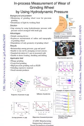
In-process Measurement of Wear of Grinding Wheelby Using Hydrodynamic Pressure • Background and problem • Monitoring of grinding wheel wear for precision grinding • Disturbance of light by working fluid • Solution • Gap sensing by using hydrodynamic pressure with pressure sensor arranged with small gap • Advantages • Simple sensing device • In-process measurement of radius and topography of grinding wheel • Dependence of only geometry of grinding wheel • Results • Relationship among pressure, gap and speed • Enable to run-out by arranging several sensors • Standard deviation of 1 mm in measured radii • Enable to detect loading, shedding and dulling • Applicable field • Plunge grinding • Creep-feed grinding • High precision grinding such as ELID • Grinding expensive material • Small-amount products Principle of measurement by using hydrodynamic pressure Experimental apparatus Examples of outputs of sensors Influence of grain size Trajectory of pressure to gap Detection of loading of grinding wheel Dispersion of measured pressure Average pressure vs. gap (C)2001 Manufacturing Engineering Laboratory, Toyota Technological Institute
Equi-potential power Divided power Equii-potential power Divided power Three-dimensional Form Generationby Dot-matrix Electrical Discharge Machining • Background and problem • Needs for rapid production system for metals • Difficulty in production of tool electrode to machine small shape • Solution • Shaping profile of bundled electrodes by controlling their length and scanning them as one electrode • Advantages • Enable to skip making process of electrode • Mechanical strength of electrode • Enable to compensate electrodes for heavy wear by feeding them • Use of thin wire for electrodes • Results • Machining 3D shape with 6 thin electrodes • Less cracks by divided power because of discharge dispersion • Applicable fields • Micromachining • Micromold fabrication • Rapid prototyping for metals Quill of electrical discharge machine Concept of dot-matrix electrical discharge machining Appearance of machining unit System configuration Positioning sequence of electrodes Designed shape Machining sequence Types of power supply for dot-matrix EDM Result of machining Example of machining Improvement of waviness Discharge dispersion (C)2001 Manufacturing Engineering Laboratory, Toyota Technological Institute
Precision Positioning Table Employing Parallel Mechanismfor Scanning Probe Microscope • Background and Problem • Cutting machine for nanometer depth of cut • unavoidable tilt of tube type piezoelectric actuator in general scanning probe microscope (SPM) • Solution • Stewart platform type parallel mechanism controlled by induced charge feedback method • Advantages • 6 degrees of freedom • High resolution in z because of small elevation angle • Flexible tool path • Enable to use in vacuum because of no slipping element • Results • Smaller tilt (1/10 to tube type) • High positioning accuracy (16 nm in z) • Linearity within 20×20 mm by semi-closed loop control • Applicable fields • Ductile mode cutting of brittle materials • Micromachininig • Fine motion stage for SPM Appearance of device Sectional view Setup for atomic force microscope Specifications Size: 16016085 mm Mass of table: 24 g Movable range: 100 mm in xy, 20 mm in z Resonance frequency: 100 Hz in xy, 75 Hz in z Degrees of freedom: 6 Actuators: Piezoelectric actuators Magnification: 12.5 Block diagram of control system Cross-talk ratio AFM image of diffraction gratings Force curve on Silicon (C)2001 Manufacturing Engineering Laboratory, Toyota Technological Institute