HBD Air Cooling System
130 likes | 331 Views
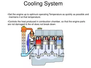
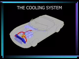
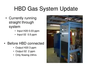
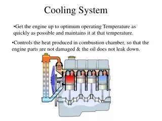
HBD Air Cooling System. TK Hemmick for the HBD group 8/25/06. Why is Cooling Needed? . The noise debugging of the HBD showed that RF shield covers must be applied above the pre-amp cards. These covers give excellent noise performance but trap heat. The pre-amps & LDO regulators reach 50-60C.

HBD Air Cooling System
E N D
Presentation Transcript
HBD Air Cooling System TK Hemmick for the HBD group 8/25/06
Why is Cooling Needed? • The noise debugging of the HBD showed that RF shield covers must be applied above the pre-amp cards. • These covers give excellent noise performance but trap heat. • The pre-amps & LDO regulators reach 50-60C. • These temperatures are not a fire hazard, but they would limit the lifetime of the pre-amps. • So…we designed a way to cool them.
How can cooling be accomplished? • The covers: • Block normal convention (the problem). • Form a channel for air (the solution). • There are 6 covers around the azimuth and 6 gaps between the covers. • The gaps have sufficient room for a 3/8” tube from which to supply air. • How much air? • How to deliver air?
Overview of Information • System requirements: • Power load handling. • Amount of air required (theory) • Amount of air required (measurement) • Air handling system. • Pressure & Flow (theory) • Pressure & flow (measurement) • System parts (Prototype & Proposal) • Exploded view of parts. • Materials list. • MSDS links.
Power load. • One preamp card requires: • +6V at 1.8 A • -6V at 1.2 A • 18 Watts • LDO regulators on board can handle higher temp, preamps cannot. • Pre-amps = +5V at 1.8 A & -5V at 1.2 A • 15 Watts. • Air flow should remove 15 Watts from every board.
Air requirements (theory) • One board… • 15 Watts = 15 Joules/sec. • Air can be approximated well as an ideal diatomic gas (CP=7/2 R) • 15 Joules in one second. • Allow 20 degree rise. • Requires 0.64 liters in one second. • Requires ~40 l/min~80 cfh NOTE: Upper limit (ignores natural convective cooling)
Air requirements (measurement) • One circuit card was outfitted with a small tube to spread air flow over card. • Tube = 3/8” diameter, 2.5” water, 5 small holes (uniform flow w/ reasonable pressure & small holes) • Pre-amp temp as a function of flow is plotted. • 50 cfh is good target for cooling each board. • 6 board per side = 300 cfh = 5 cfm per side.
Pressure and Flow (theory) • P in final tube = 2.5” water • DPtot <0.2” water to assure uniform air delivery. • F = 5 cfm, L=15” (conservative) • h=1.8x10⁻⁵ Pascal x sec • r = 0.26 inches (d=0.52 inches). • Flow is not purely laminar… • Set ID of tubing to ¾” F 5/6F 4/6F 3/6F 2/6F 1/6F http://www.google.com/search?hl=en&lr=&client=firefox-a&rls=org.mozilla%3Aen-US%3Aofficial&q=2*%28%2815*5+cubic+feet+per+minute+*+8+*+1.8E-5+pascal+seconds+*+15+inches%29%2F%286*pi*0.4+torr%29%29%5E0.25+in+inches&btnG=Search
Pressure & Flow (measurement-1) • Assemble prototype manifold. • All tubing dimensions correct. • Measure air flow parameters.
Pressure & Flow (measurement-2) • Measured parameters: • 5 cfm flow. • Pressure in tubes = 2.5” water. • 0.1” water difference from first to last tube. • 6” water is pressure at supply. • Design parameters met exactly. 100% success. Air flow uniform in all holes.
Exploded (Prototype) Part List • Tubing • ¾” ID Poly-flow tubing • ½” ID Latex (surgical) tubing • Nylon plumbing • TEE, coupling; hose barb; elbow; cap. • PTEG Plastic: • 3/8” nominal tubing. Link pointing to MSDS Files: http://skipper.physics.sunysb.edu/HBD/MSDS/
Example Commercial Blower… • The above small (2” x 2”) commercial blower meets all the specifications for our needs. • http://www.acal-radiatron.com/download/micronel/u51dl-tec.pdf • This will be evaluated and compared to other similar units. • Blower selection will be discussed separately.
Proposed System • Manifold: • PVC pipe, ¾” ID, running underneath HBD cable tray. • Nylon NPT3/8”Hose Barb at 6 locations. • Jumper (manifold individual tube) • 3/8” latex surgical tubing. • Flow tube: • 3/8” ID mylar tube (0.010” thick wall) • Nylon cap.