Download
1 / 47
470 likes | 549 Views
Learn VHDL structural modeling with generate statements and design examples. Understand multiplexers, decoders, and processors.

E N D
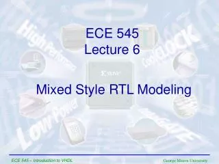
ECE 545 Lecture 6 Mixed Style RTL Modeling ECE 545 – Introduction to VHDL
Structural Modeling: Generate Statements Examples ECE 545 – Introduction to VHDL
Example 1 s 0 s 1 w 0 w 3 s w 2 4 s 3 w 7 f w 8 w 11 w 12 w 15 ECE 545 – Introduction to VHDL
A 4-to-1 Multiplexer LIBRARY ieee ; USE ieee.std_logic_1164.all ; ENTITY mux4to1 IS PORT ( w0, w1, w2, w3 : IN STD_LOGIC ; s : IN STD_LOGIC_VECTOR(1 DOWNTO 0) ; f : OUT STD_LOGIC ) ; END mux4to1 ; ARCHITECTURE Dataflow OF mux4to1 IS BEGIN WITH s SELECT f <= w0 WHEN "00", w1 WHEN "01", w2 WHEN "10", w3 WHEN OTHERS ; END Dataflow ; ECE 545 – Introduction to VHDL
Straightforward code for Example 1 LIBRARY ieee ; USE ieee.std_logic_1164.all ; ENTITY Example1 IS PORT ( w : IN STD_LOGIC_VECTOR(0 TO 15) ; s : IN STD_LOGIC_VECTOR(3 DOWNTO 0) ; f : OUT STD_LOGIC ) ; END Example1 ; ECE 545 – Introduction to VHDL
Straightforward code for Example 1 ARCHITECTURE Structure OF Example1 IS COMPONENT mux4to1 PORT ( w0, w1, w2, w3 : IN STD_LOGIC ; s : IN STD_LOGIC_VECTOR(1 DOWNTO 0) ; f : OUT STD_LOGIC ) ; END COMPONENT ; SIGNAL m : STD_LOGIC_VECTOR(0 TO 3) ; BEGIN Mux1: mux4to1 PORT MAP ( w(0), w(1), w(2), w(3), s(1 DOWNTO 0), m(0) ) ; Mux2: mux4to1 PORT MAP ( w(4), w(5), w(6), w(7), s(1 DOWNTO 0), m(1) ) ; Mux3: mux4to1 PORT MAP ( w(8), w(9), w(10), w(11), s(1 DOWNTO 0), m(2) ) ; Mux4: mux4to1 PORT MAP ( w(12), w(13), w(14), w(15), s(1 DOWNTO 0), m(3) ) ; Mux5: mux4to1 PORT MAP ( m(0), m(1), m(2), m(3), s(3 DOWNTO 2), f ) ; END Structure ; ECE 545 – Introduction to VHDL
Modified code for Example 1 ARCHITECTURE Structure OF Example1 IS COMPONENT mux4to1 PORT ( w0, w1, w2, w3 : IN STD_LOGIC ; s : IN STD_LOGIC_VECTOR(1 DOWNTO 0) ; f : OUT STD_LOGIC ) ; END COMPONENT ; SIGNAL m : STD_LOGIC_VECTOR(0 TO 3) ; BEGIN G1: FOR i IN 0 TO 3 GENERATE Muxes: mux4to1 PORT MAP ( w(4*i), w(4*i+1), w(4*i+2), w(4*i+3), s(1 DOWNTO 0), m(i) ) ; END GENERATE ; Mux5: mux4to1 PORT MAP ( m(0), m(1), m(2), m(3), s(3 DOWNTO 2), f ) ; END Structure ; ECE 545 – Introduction to VHDL
Example 2 w y w y 0 0 0 0 w y w y 1 1 1 1 y y 2 2 y y En 3 3 y w y 4 0 0 w y y 1 1 5 y y 2 6 w w y y y 2 En 0 0 3 7 w w y 3 1 1 y 2 y w w y y En En 8 0 0 3 y w y 9 1 1 y y 2 10 y y En 3 11 y w y 12 0 0 y w y 13 1 1 y y 2 14 y y En 3 15 ECE 545 – Introduction to VHDL
A 2-to-4 binary decoder LIBRARY ieee ; USE ieee.std_logic_1164.all ; ENTITY dec2to4 IS PORT ( w : IN STD_LOGIC_VECTOR(1 DOWNTO 0) ; En : IN STD_LOGIC ; y : OUT STD_LOGIC_VECTOR(0 TO 3) ) ; END dec2to4 ; ARCHITECTURE Dataflow OF dec2to4 IS SIGNAL Enw : STD_LOGIC_VECTOR(2 DOWNTO 0) ; BEGIN Enw <= En & w ; WITH Enw SELECT y <= "1000" WHEN "100", "0100" WHEN "101", "0010" WHEN "110", "0001" WHEN "111", "0000" WHEN OTHERS ; END Dataflow ; ECE 545 – Introduction to VHDL
VHDL code for Example 2 (1) LIBRARY ieee ; USE ieee.std_logic_1164.all ; ENTITY dec4to16 IS PORT (w : IN STD_LOGIC_VECTOR(3 DOWNTO 0) ; En : IN STD_LOGIC ; y : OUT STD_LOGIC_VECTOR(0 TO 15) ) ; END dec4to16 ; ECE 545 – Introduction to VHDL
VHDL code for Example 2 (2) ARCHITECTURE Structure OF dec4to16 IS COMPONENT dec2to4 PORT ( w : IN STD_LOGIC_VECTOR(1 DOWNTO 0) ; En : IN STD_LOGIC ; y : OUT STD_LOGIC_VECTOR(0 TO 3) ) ; END COMPONENT ; SIGNAL m : STD_LOGIC_VECTOR(0 TO 3) ; BEGIN G1: FOR i IN 0 TO 3 GENERATE Dec_ri: dec2to4 PORT MAP ( w(1 DOWNTO 0), m(i), y(4*i TO 4*i+3) ); G2: IF i=3 GENERATE Dec_left: dec2to4 PORT MAP ( w(i DOWNTO i-1), En, m ) ; END GENERATE ; END GENERATE ; END Structure ; ECE 545 – Introduction to VHDL
Mixed Modeling: Example ECE 545 – Introduction to VHDL
Mixed Style Modeling Concurrent Statements architecture ARCHITECTURE_NAME of ENTITY_NAME is • Here you can declare signals, constants, functions, procedures… • Component declarations • No variable declarations !! begin Concurrent statements: • Concurrent simple signal assignment • Conditional signal assignment • Selected signal assignment • Generate statement • Component instantiation statement • Process statement • inside process you can use only sequential statements end ARCHITECTURE_NAME; ECE 545 – Introduction to VHDL
Simple Processor ECE 545 – Introduction to VHDL
N-bit register with enable LIBRARY ieee ; USE ieee.std_logic_1164.all ; ENTITY regn IS GENERIC ( N : INTEGER := 8 ) ; PORT ( D : IN STD_LOGIC_VECTOR(N-1 DOWNTO 0) ; En : IN STD_LOGIC ; Clock : IN STD_LOGIC ; Q : OUT STD_LOGIC_VECTOR(N-1 DOWNTO 0) ) ; END regn ; ARCHITECTURE Behavior OF regn IS BEGIN PROCESS BEGIN IF (Clock'EVENT AND Clock = '1‘) THEN IF En = '1' THEN Q <= D ; END IF; END IF ; END PROCESS ; END Behavior ; ECE 545 – Introduction to VHDL
N-bit tristate buffer LIBRARY ieee ; USE ieee.std_logic_1164.all ; ENTITY trin IS GENERIC ( N : INTEGER := 8 ) ; PORT ( X : IN STD_LOGIC_VECTOR(N-1 DOWNTO 0) ; En : IN STD_LOGIC ; Y : OUT STD_LOGIC_VECTOR(N-1 DOWNTO 0) ) ; END trin ; ARCHITECTURE Behavior OF trin IS BEGIN Y <= (OTHERS => 'Z') WHEN En = '0' ELSE X ; END Behavior ; ECE 545 – Introduction to VHDL
Packages and component declarations LIBRARY ieee ; USE ieee.std_logic_1164.all ; PACKAGE exec_components IS COMPONENT regn -- register GENERIC ( N : INTEGER := 8 ) ; PORT ( D : IN STD_LOGIC_VECTOR(N-1 DOWNTO 0) ; En : IN STD_LOGIC ; Clock : IN STD_LOGIC ; Q : OUT STD_LOGIC_VECTOR(N-1 DOWNTO 0) ) ; END COMPONENT ; COMPONENT trin -- tri-state buffers GENERIC ( N : INTEGER := 8 ) ; PORT ( X : IN STD_LOGIC_VECTOR(N-1 DOWNTO 0) ; En : IN STD_LOGIC ; Y : OUT STD_LOGIC_VECTOR(N-1 DOWNTO 0) ) ; END COMPONENT ; END exec_components ; ECE 545 – Introduction to VHDL
Processor – Execution Unit (1) LIBRARY ieee ; USE ieee.std_logic_1164.all ; USE work.exec_components.all ; USE ieee.std_logic_signed.all ; ENTITY Proc_Exec IS PORT ( Data : IN STD_LOGIC_VECTOR(7 DOWNTO 0) ; Clock : IN STD_LOGIC ; Rin : IN STD_LOGIC_VECTOR(0 to 3); Rout : IN STD_LOGIC_VECTOR(0 to 3); Ain : IN STD_LOGIC ; Gin : IN STD_LOGIC ; Gout : IN STD_LOGIC ; AddSub : IN STD_LOGIC; Extern : IN STD_LOGIC; BusWires : INOUT STD_LOGIC_VECTOR(7 DOWNTO 0) ; END Proc_Exec ; ECE 545 – Introduction to VHDL
Processor – Execution Unit (2) ARCHITECTURE Mixed OF Proc_Exec IS TYPE RegArray is ARRAY(0 to 3) of STD_LOGIC_VECTOR(7 downto 0); SIGNAL R : RegArray; SIGNAL A : STD_LOGIC_VECTOR(7 DOWNTO 0) ; SIGNAL G : STD_LOGIC_VECTOR(7 DOWNTO 0) ; SIGNAL Sum : STD_LOGIC_VECTOR(7 DOWNTO 0) ; ECE 545 – Introduction to VHDL
Processor – Execution Unit (3) BEGIN G1: FOR i IN 0 TO 3 GENERATE Regs: regn PORT MAP ( D => BusWires, En => Rin(i), Clock => Clock, Q => R(i)) ; Trins: trin PORT MAP ( X => R(i), En => Rout(i), Y => BusWires) ; END GENERATE ; ECE 545 – Introduction to VHDL
Processor – Execution Unit (4) RegA: regn PORT MAP ( D => BusWires, En => Ain, Clock => Clock, Q => A) ; RegG: regn PORT MAP ( D => Sum, En => Gin, Clock => Clock, Q => G) ; triG: trin PORT MAP ( X => G, En => Gout, Y => BusWires) ; ECE 545 – Introduction to VHDL
Processor – Execution Unit (5) ALU: WITH AddSub Select Sum <= A + B WHEN ‘0’, A – B WHEN OTHERS; Tri_extern: trin PORT MAP ( X => Data, En => Extern, Y => BusWires) ; END Mixed; ECE 545 – Introduction to VHDL
Processor – Control Unit (1) LIBRARY ieee ; USE ieee.std_logic_1164.all ; USE work.control_components.all ; ENTITY Proc_Control IS PORT ( Func : IN STD_LOGIC_VECTOR(1 TO 6) ; w : IN STD_LOGIC ; Clock : IN STD_LOGIC ; Reset : IN STD_LOGIC ; Rin : OUT STD_LOGIC_VECTOR(0 to 3); Rout : OUT STD_LOGIC_VECTOR(0 to 3); Ain : OUT STD_LOGIC ; Gin : OUT STD_LOGIC ; Gout : OUT STD_LOGIC ; AddSub : OUT STD_LOGIC; Extern : OUT STD_LOGIC; Done : OUT STD_LOGIC; END Proc_Control ; ECE 545 – Introduction to VHDL
Processor Instructions ECE 545 – Introduction to VHDL
Processor ECE 545 – Introduction to VHDL
Counter of instruction clock cycles T T T T 0 1 2 3 y y y y 0 1 2 3 2-to-4 decoder w w En 1 0 Count 1 Q Q 1 0 Clock Up-counter Clear Reset ECE 545 – Introduction to VHDL
The Function Register and Decoders I I I I X X X X Y Y Y Y 0 1 2 3 0 1 2 3 0 1 2 3 y y y y y y y y y y y y 0 1 2 3 0 1 2 3 0 1 2 3 2-to-4 decoder 2-to-4 decoder 2-to-4 decoder w w w w w w En En En 1 0 1 0 1 0 1 1 1 Clock Function Register FR in f f Rx Rx Ry Ry 1 0 1 0 1 0 Function ECE 545 – Introduction to VHDL
Control signals asserted in each operation and time step ECE 545 – Introduction to VHDL
Packages and component declarations LIBRARY ieee ; USE ieee.std_logic_1164.all ; PACKAGE control_components IS COMPONENT dec2to4 PORT (w : IN STD_LOGIC_VECTOR(1 DOWNTO 0) ; En : IN STD_LOGIC ; y : OUT STD_LOGIC_VECTOR(0 TO 3) ) ; END COMPONENT ; COMPONENT upcount GENERIC ( N : INTEGER := 2 ) ; PORT ( Clock : IN STD_LOGIC ; Reset : IN STD_LOGIC ; Q : OUT STD_LOGIC_VECTOR(N-1 DOWNTO 0) ) ; END COMPONENT ; END control_components ; ECE 545 – Introduction to VHDL
N-bit Up Counter (1) LIBRARY ieee ; USE ieee.std_logic_1164.all ; USE ieee.std_logic_unsigned.all ; ENTITY upcount IS GENERIC ( N : INTEGER := 2 ) ; PORT (Clock : IN STD_LOGIC ; Reset : IN STD_LOGIC ; Q : BUFFER STD_LOGIC_VECTOR(N-1 DOWNTO 0) ) ; END upcount ; ECE 545 – Introduction to VHDL
N-bit Up Counter (2) ARCHITECTURE Behavior OF upcount IS BEGIN upcount: PROCESS ( Clock ) BEGIN IF (Clock'EVENT AND Clock = '1') THEN IF Reset = '1' THEN Q <= (OTHERS => ‘0’); ELSE Q <= Q + 1 ; END IF ; END IF; END PROCESS; END Behavior ; ECE 545 – Introduction to VHDL
Processor – Control Unit (2) ARCHITECTURE Mixed OF Proc_Control IS SIGNAL Clear : STD_LOGIC; SIGNAL Count: STD_LOGIC_VECTOR(1 DOWNTO 0); SIGNAL T : STD_LOGIC_VECTOR(0 TO 3); SIGNAL FRin : STD_LOGIC; SIGNAL FuncReg: IN STD_LOGIC_VECTOR(5 DOWNTO 0) ; SIGNAL I : STD_LOGIC_VECTOR(0 TO 3); SIGNAL X : STD_LOGIC_VECTOR(0 TO 3); SIGNAL Y : STD_LOGIC_VECTOR(0 TO 3); SIGNAL High : STD_LOGIC; ECE 545 – Introduction to VHDL
Counter of instruction clock cycles T T T T 0 1 2 3 y y y y 0 1 2 3 2-to-4 decoder w w En 1 0 Count 1 Q Q 1 0 Clock Up-counter Clear Reset ECE 545 – Introduction to VHDL
Processor – Control Unit (3) BEGIN counter: upcount PORT MAP ( Clock => Clock, Reset => Clear, Q => Count ) ; Clear <= Reset OR Done OR (NOT w AND T(0)) ; High <= '1' ; decT: dec2to4 PORT MAP ( w => Count, En => High, y => T ); ECE 545 – Introduction to VHDL
The Function Register and Decoders I I I I X X X X Y Y Y Y 0 1 2 3 0 1 2 3 0 1 2 3 y y y y y y y y y y y y 0 1 2 3 0 1 2 3 0 1 2 3 2-to-4 decoder 2-to-4 decoder 2-to-4 decoder w w w w w w En En En 1 0 1 0 1 0 1 1 1 Clock Function Register FR in f f Rx Rx Ry Ry 1 0 1 0 1 0 Function ECE 545 – Introduction to VHDL
Processor – Control Unit (4) functionreg: regn GENERIC MAP ( N => 6 ) PORT MAP ( D => Func, En => FRin, Clock => Clock, Q => FuncReg ) ; FRin <= w AND T(0); decI: dec2to4 PORT MAP ( w =>FuncReg(5 DOWNTO 4), En => High, y => I ) ; ECE 545 – Introduction to VHDL
Processor – Control Unit (5) decX: dec2to4 PORT MAP ( w => FuncReg(3 DOWNTO 2), En => High, y => X ) ; decY: dec2to4 PORT MAP ( w => FuncReg(1 DOWNTO 0), En => High, y => Y ) ; ECE 545 – Introduction to VHDL
Control signals asserted in each operation and time step ECE 545 – Introduction to VHDL
Processor – Control Unit (5) control_signals: PROCESS (T, I, X, Y) BEGIN Extern <= '0' ; Done <= '0' ; Ain <= '0' ; Gin <= '0' ; Gout <= '0' ; AddSub <= '0' ; Rin <= "0000" ; Rout <= "0000" ; CASE T IS WHEN “1000” => null; -- no signals asserted in the time step T0 WHEN “0100” => CASE I IS WHEN “1000" => -- Load Extern <= '1' ; Rin <= X ; Done <= '1' ; WHEN "0100" => -- Move Rout <= Y ; Rin <= X ; Done <= '1' ; WHEN OTHERS => -- Add, Sub Rout <= X ; Ain <= '1' ; END CASE ; END PROCESS; ECE 545 – Introduction to VHDL
Processor – Control Unit (6) WHEN “0010” => CASE I IS WHEN “0010" => -- Add Rout <= Y ; Gin <= '1' ; WHEN “0001" => -- Sub Rout <= Y ; AddSub <= '1' ; Gin <= '1' ; WHEN OTHERS => -- Load, Move END CASE ; WHEN OTHERS => -- define signals asserted in time step T3 CASE I IS WHEN “1000" => -- Load WHEN "0100" => -- Move WHEN OTHERS => -- Add, Sub Gout <= '1' ; Rin <= X ; Done <= '1' ; END CASE ; END CASE ; ECE 545 – Introduction to VHDL
Processor – Control Unit (7) END PROCESS; END Mixed; ECE 545 – Introduction to VHDL
Using Arrays of Test Vectors In Testbenches ECE 545 – Introduction to VHDL
Testbench (1) LIBRARY ieee; USE ieee.std_logic_1164.all; ENTITY sevenSegmentTB is END sevenSegmentTB; ARCHITECTURE testbench OF sevenSegmentTB IS COMPONENTsevenSegment PORT ( bcdInputs: INSTD_LOGIC_VECTOR (3 DOWNTO 0); seven_seg_outputs: OUTSTD_LOGIC_VECTOR(6 DOWNTO 0); ); end COMPONENT; CONSTANT PropDelay: time := 40 ns; CONSTANT SimLoopDelay: time := 10 ns; ECE 545 – Introduction to VHDL
Testbench (2) TYPE vector ISRECORD bcdStimulus: STD_LOGIC_VECTOR(3 downto 0); sevSegOut: STD_LOGIC_VECTOR(6 downto 0); END RECORD; CONSTANT NumVectors: INTEGER:= 10; TYPE vectorArray is ARRAY (0 TO NumVectors - 1) OF vector; CONSTANT vectorTable: vectorArray := ( (bcdStimulus => "0000", sevSegOut => "0000001"), (bcdStimulus => "0001", sevSegOut => "1001111"), (bcdStimulus => "0010", sevSegOut => "0010010"), (bcdStimulus => "0011", sevSegOut => "0000110"), (bcdStimulus => "0100", sevSegOut => "1001100"), (bcdStimulus => "0101", sevSegOut => "0100100"), (bcdStimulus => "0110", sevSegOut => "0100000"), (bcdStimulus => "0111", sevSegOut => "0001111"), (bcdStimulus => "1000", sevSegOut => "0000000"), (bcdStimulus => "1001", sevSegOut => "0000100") ); ECE 545 – Introduction to VHDL
Testbench (3) SIGNAL StimInputs: STD_LOGIC_VECTOR(3 downto 0); SIGNAL CaptureOutputs: STD_LOGIC_VECTOR(6 downto 0); BEGIN u1: sevenSegment PORT MAP ( bcdInputs => StimInputs, seven_seg_outputs => CaptureOutputs); ECE 545 – Introduction to VHDL
Testbench (4) LoopStim: PROCESS BEGIN FOR i in 0 TO NumVectors-1LOOP StimInputs <= vectorTable(i).bcdStimulus; WAITFOR PropDelay; ASSERT CaptureOutputs == vectorTable(i).sevSegOut REPORT“Incorrect Output” SEVERITYerror; WAIT FOR SimLoopDelay; END LOOP; ECE 545 – Introduction to VHDL
Testbench (5) WAIT; END PROCESS; END testbench; ECE 545 – Introduction to VHDL