Download
1 / 34
350 likes | 537 Views
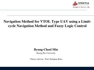
Navigation Method for VTOL Type UAV using a Limit-cycle Navigation Method and Fuzzy Logic Control. Byung-Cheol Min Kyung Hee University (Thesis Advisor : Prof. Donghan Kim). Contents. Introduction Path Planning Algorithm UAV (Unmanned Aerial Vehicle) Path Tracking Method Conclusion.

E N D
Navigation Method for VTOL Type UAV using a Limit-cycle Navigation Method and Fuzzy Logic Control Byung-CheolMin Kyung Hee University (Thesis Advisor : Prof. Donghan Kim)
Contents • Introduction • Path Planning Algorithm • UAV (Unmanned Aerial Vehicle) • Path Tracking Method • Conclusion Introduction
1. Introduction - What is a navigation method? Path Tracking Navigation Path Planning - Applications (c) Commercial Airplanes (a) Unmanned Aerial Vehicles (b) Unmanned Ground Vehicles Introduction
1. Introduction Classic Path Planning Approach - Potential Field Method - Limit-cycle Navigation Method (d) Simulation on the Limit-Cycle navigation method (a) r = 30 (c) r = 70 (b) r = 50 Introduction
2. Path Planning Algorithm The Basic Concept of Limit-cycle method in three dimensions (3D) dx = current x position – obstacle x position dy = current y position – obstacle y position dz= current z position – center of the obstacle z position Dh is a tangent line between the current position and the tangent point of an obstacle circle. center of the obstacle dz With this obtained angle, the input of the z-value can be calculated as dx dy Δy Δx Dh Δh current position Δx and Δy values are obtained by the original limit-cycle navigation method. Path Planning Algorithm
2. Path Planning Algorithm • Problem Statement Although the proposed method verified a variety of merits in 3D, it also showed several drawbacks. 1. The method usually draws the path with setting previous along the center of obstacle’s height, depicted in (a). 2. The method generates the path only by avoiding to the side of the obstacle, depicted in (c). (b) possible paths (a) unsuitable path (c) unsuitable path (d) suitable path Path Planning Algorithm
2. Path Planning Algorithm Path Planning Based on the Methods of Ray Tracing and Limit-Cycle START Ray tracing is an algorithm that shoots beams of light to determine the accurate location and the size of the objects. In this paper, however, the method is used for the aircraft to find the shortest path to reach the destination while avoiding the obstacle. Put the initial point for Pi and the destination point for Pd Render the obstacle Ray Tracing Draw a line P(t) between Pi and Pd Path Planning Path Planning Algorithm
2. Path Planning Algorithm Path Planning Based on the Methods of Ray Tracing and Limit-Cycle START (1) Put the initial point for Pi and the destination point for Pd Eq. (1) can be expressed as Render the obstacle (2) Ray Tracing The coefficients a, b, and c in Eq. (2) can be expressed as follows. Draw a line P(t) between Pi and Pd (3) No Does two Intersections exist? Yes By solving the discriminant, we can know whether the line P(t) intersects the sphere or not. Generate a straight path Path Planning END Path Planning Algorithm
2. Path Planning Algorithm Path Planning Based on the Methods of Ray Tracing and Limit-Cycle START Put the initial point for Pi and the destination point for Pd Render the obstacle Ray Tracing Draw a line P(t) between Pi and Pd (a) line P(t) from Pi toPd No Does two Intersections exist? When the horizontal direction is chosen, limit cycle is generated on the x-y plane. When the vertical direction is chosen, limit cycle is generated on the x-z plane. Yes Generate a straight path Decide the path between a horizontal direction and a vertical direction Path Planning END (b) x-y plane, z=0 (c) x-z plane, y=0 Path Planning Algorithm
2. Path Planning Algorithm Path Planning Based on the Methods of Ray Tracing and Limit-Cycle START Put the initial point for Pi and the destination point for Pd Render the obstacle Ray Tracing Draw a line P(t) between Pi and Pd The huge gap occurs if the radius of limit cycle is calculated based on the center of the obstacle. No Does two Intersections exist? Yes Generate a straight path Decide the path between a horizontal direction and a vertical direction Path Planning Calculate a radius of the limit cycle based on the line Generate a path by limit cycle Only slight difference occurs between the hypothetical limit cycle in 3D and the proposed limit cycle in 2D. END Path Planning Algorithm
2. Path Planning Algorithm Simulation Result 1 Two suitable paths were generated among numerous paths that can be planned by limit cycle method. And then, the shortest path was decided by comparing two distances depicted as a solid line. 82.43 m 89.1 m (a) Path Planning Algorithm
2. Path Planning Algorithm Simulation Result 2 • The three paths from different initial points is successfully generated. • There are no gaps between the sphere and three paths. Thus, each of paths is smooth enough for UAVs to fly because of limit cycle characteristics. (a) (b) Path Planning Algorithm
2. Path Planning Algorithm Path Planning for Dynamic Obstacle Avoidance: collision detection method • An algorithm to generate a path to avoid dynamic obstacles is mainly comprised of a collision detection method and standard rules of airplane traffic. (1) Velocity vector (2) Position of moving object (3) Calculate the time twhenthe distance d between P(t) and O(t) equals to rP+ rO (a) Path Planning Algorithm
2. Path Planning Algorithm Path Planning for Dynamic Obstacle Avoidance: standard rules of airplane traffic In case there are more than two UAVs in the same operation area, standard rules to control their traffic are necessary. • “Right of way” of Federal Aviation Regulation (FAR) 91.113 to collision avoidance • “Rules of the air” of the International Civil Aviation Organization (ICAO) annex 2 “If both airplanes approach from opposite sides, they are supposed to give way by turning right away from each other to avoid a collision, and if flying airplanes come into conflicting paths side by side, the left airplane turns right to yield.” Path Planning Algorithm
2. Path Planning Algorithm Collision Detection Method Similarly, we set up the standard rules of airplane traffic as follows: • If two UAVs approach from opposite sides (i,e., more than 90 degrees), the UAV is supposed to give way by turning right away from the moving obstacle to avoid a collision. (b) Path Planning Algorithm
2. Path Planning Algorithm Standard Rules of Airplane Traffic • If the dynamic obstacle comes into conflicting the UAV's path within less than 90 degrees, the UAV waits for a while to yield. (c) Path Planning Algorithm
2. Path Planning Algorithm Simulation Result 3 • the angle between the moving direction of the UAV and the obstacle was set for bigger than 90 degrees. • The path was generated at the predicted position of a collision (42, 52) with the supposition that an obstacle exists at that position. (a) Path Planning Algorithm
3. UAV(Unmanned Aerial Vehicle) Common UAV Configurations Fixed-wing Type Vertical Take-Off and Landing Type (VTOL Type) UAV
3. UAV(Unmanned Aerial Vehicle) Basic Principles of the Quad-rotor UAV (b) Pitching & rolling configuration (a) Hovering configuration For a hovering flight, the four driven forces are F1(0) +F2 (0) + F3(0) + F4(0) = (c) Yawing configuration UAV
3. UAV(Unmanned Aerial Vehicle) The Dynamic Modeling of the Quad-rotor UAV 2) Equations of the translational motion in the earth frame are derived by the Newton’s laws 1) The rotational transformation matrix between the earth-frame {E} and the body frame {B} 3) Resultant equations of motion as follows 4) Control inputs of the model (a) The coordinate system with an earth frame {E} and a body frame {B} UAV
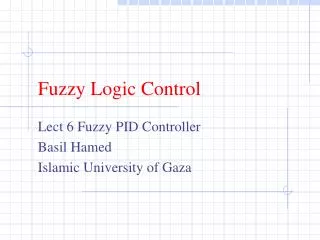
4. Path Tracking Method Fuzzy Logic Control • To control thrust and attitude of the VTOL Type UAV, which mostly affect its position, fuzzy logic control (FLC) is proposed. • The FLC, which is activated after generating the path, will be in charge of controlling the overall system of the quad-rotor UAV so that it can move to any desired position effectively. (a) Typical Fuzzy Logic Control (FLC) (b) The path tracking scheme Path Tracking Method
4. Path Tracking Method Fuzzy Logic Control Nine Fuzzy Logic Controllers (FLCs) were used to handle nonlinear system. Path Tracking Method
4. Path Tracking Method Simulation Result 1 (b) The each velocity ratio of x-y-z axes per time axis based while the quad-rotor UAV is ascending. (c) The each position of x-y-z axes per time axis based while the quad-rotor UAV is ascending. (a) The traces of path tracking by the quad-rotor UAV while ascending using FLC. Path Tracking Method
4. Path Tracking Method Simulation Result 2 • (e) The each velocity ratio of x-y-z axes per time axis based while the quad-rotor UAV is descending. (f) The each position of x-y-z axes per time axis based while the quad-rotor UAV is descending. (d) The traces of path tracking by the quad-rotor UAV while descending using FLC. Path Tracking Method
4. Path Tracking Method Simulation Result 3 (a) The result of a simulation on the proposed navigation method: There are three different initial positions and the same destination. ‘’ indicates way points from the initial position of the UAV to its destination. Path Tracking Method
4. Path Tracking Method Problem with Simulation Result 3 (b) An enlarged portion of the problem of path tracking. (c) The each velocity ratio of x-y-z axes per time axis based while the quad-rotor UAV is flying toward the destination. There is a problem that the UAV repeats stop-and-go at regular intervals. Path Tracking Method
4. Path Tracking Method Method to Solve the Problem with Simulation Result 3 Spheres centered at the way points are drawn in the form of ,where x, y, and z represent the position of the way point (desired position), and i means the order of way points, and r means a radius of sphere. When the UAV passes the ith sphere, the current desired position (xi, yi, zi) is changed to the following desired position (xi+1, yi+1, zi+1). Path Tracking Method
4. Path Tracking Method Simulation Result 4 (a) The result of a simulation on the new path tracking solving the problem that the UAV repeats stop-and go around the way points Path Tracking Method
4. Path Tracking Method Simulation Result 5 (b) An enlarged portion of the simulation result (c) The each velocity ratio of x-y-z axes per time axis based while the quad-rotor UAV is flying toward the destination Path Tracking Method
4. Path Tracking Method Simulation on Dynamic Obstacle Avoidance: the Second Standard Rule of Airplane Traffic (b) Dynamic Obstacle Avoidance: the Second Standard Rule of Airplane Traffic (a) The result of dynamic obstacle avoidance in a case where the obtacle comes into a conflicting the UAV's path within less than 90 degree Path Tracking Method
4. Path Tracking Method Simulation on Dynamic Obstacle Avoidance: the Second Standard Rule of Airplane Traffic (a) Obstacle (c) The each position of the UAV (b) UAV Path Tracking Method
5. Conclusion • Extension of the original limit-cycle navigation method of three dimensional spaces • New path planning algorithm based on the methods of ray tracing and the extended limit-cycle navigation method • Algorithm comprised of a collision detection method and standard rules of airplane traffic that generates a path to avoid collisions with dynamic obstacles • Fuzzy logic control method in order for the UAV to converge quickly on the desired position • Solving the problem that the UAV repeats stop-and go around the way points, using virtual spheres Conclusion
Limit-cycle Matlab Source function [x, y, z] = limtcycle(Pos_x, Pos_y, Pos_z, ObPosx , ObPosy, ObPosz, r, direct) dx = (Pos_x -ObPosx); dy = (Pos_y -ObPosy); dz = (ObPosz - Pos_z); Dh = sqrt(dx^2 + dy^2); if(direct == -1) ddx = -dy*r^2 + dx * (r^2 - dx^2 - dy^2); ddy = dx*r^2 + dy * (r^2 - dx^2 - dy^2); else ddx = dy*r^2 + dx * (r^2 - dx^2 - dy^2); ddy = -dx*r^2 + dy * (r^2 - dx^2 - dy^2); end theta_xy = atan2(ddy,ddx); Theta_z = atan2(dz,Dh); Del = 5; Del_x = Del*cos(theta_xy); Del_y = Del*sin(theta_xy); Del_h = Del*tan(Theta_z); x = Del_x + Pos_x; y = Del_y + Pos_y; z = Del_h + Pos_z; end
Publications -5 Journal Publications, 5 Conference & Symposium Proceedings - Journal Publications • B.C. Min, and D.H. Kim, “A Navigation Method for VTOL type UAV Using Limit-cycle Navigation Method and Fuzzy Logic Control," IEEE Transactions on Systems, Man, and Cybernetics, 2010. (in preparation) • B.C. Min, M. Kim, and D. Kim, "Fuzzy Logic Path Planner and Motion Controller by Evolutionary Programming for Mobile Robots," International Journal of Fuzzy Systems, Vol. 11, No. 3, September 2009. • B.C. Min, D. Kim, Y.H. Kim, K.Y. Kim, and C. Park, "Development of Violin Self-Training Algorithm Using Fuzzy Logic," Journal of Korean Institute of Intelligent Systems, Vol. 19, No. 4, August 2009. (in Korean) • B.C. Min, C.H. Cho, K.M. Choi, and D. H. Kim, "Development of a Micro Quad-Rotor UAV for Monitoring an Indoor Environment,", Lecture Notes in Computer Science (LNCS), FIRA CIRAS 2009, Vol. 5744, pp. 262-271, August 2009. • C.H. Cho, B.C. Min, and D. H. Kim, "A Gait Generation for an Unlocked Joint Failure of the Quadruped Robot with Balance Weight," Lecture Notes in Computer Science (LNCS), FIRA CIRAS 2009, Vol. 5744, pp. 251-261, August 2009. - Conference & Symposium Proceedings • B.C. Min, H.Y. Kwon, and D.H. Kim, "Path Planning Algorithm for VTOL Type UAVs Based on the Methods of Ray Tracing and Limit Cycle," IEEE International Symposium on Computational Intelligence in Robotics and Automation (CIRA 2009), December 2009. • B.C. Min, E.J. Lee, S.H. Kang, and D.H. Kim, "Limit-cycle Navigation Method for a Quad-rotor Type UAV," Industrial Electronics, 2009. ISIE 2009, IEEE International Symposium on, pp. 1352-1357, July 2009. • S.H. Kang, B.C. Min, C.H. Cho, S.Y. Nam, and D.H. Kim, "The Position Control for Three Wheel Omni-directional Mobile Robot Using FLC," IEEK Summer Conference 2009, Vol. 32, No. 1, pp. 691-692, July 2009. (in Korean) • Y.W. Lim, B.C. Min, J.W. Kim, S.Y. Nam, and D.H. Kim, “Local-Path Planning Using the Limit-cycle Navigation Method Applied to the Edge of an Obstacle with the Edge Detection Method”, International Conference On Electronics, Information, & Communication (ICEIC 2010), April 2010. • Y.H. Kim, J.W. Kim, B.C. Min, and D.H. Kim, “Dynamic Obstacle Avoidance Using Vector Function Algorithm”, International Conference On Electronics, Information, & Communication (ICEIC 2010), April 2010.