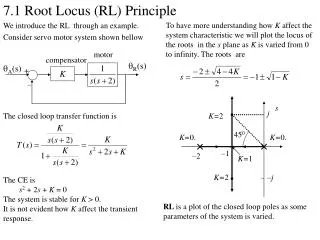
RL example
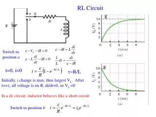
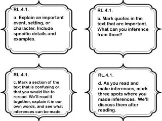
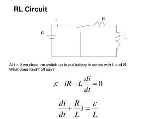
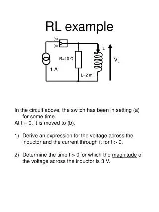
I L. R=10 Ω. V L. L=2 mH. RL example. (a). (b). 1 A. In the circuit above, the switch has been in setting (a) for some time. At t = 0, it is moved to (b). Derive an expression for the voltage across the inductor and the current through it for t > 0.

RL example
E N D
Presentation Transcript
IL R=10 Ω VL L=2 mH RL example (a) (b) 1 A • In the circuit above, the switch has been in setting (a) for some time. • At t = 0, it is moved to (b). • Derive an expression for the voltage across the inductor and the current through it for t > 0. • Determine the time t > 0 for which the magnitude of the voltage across the inductor is 3 V.
IRstart =0 1 A 1 A t= 0 (a) 1 A First we need to look at the circuit’s “pre-history” – ie where were all the voltages and currents before flipping the switch at t=0? At t = 0, the circuit is equivalent to that shown above. As the inductor is simply a piece of bent wire (!), no current flows through the resistor, and it can be disregarded when figuring out Istart, Ifinish etc So – the initial current through the inductor is 1 A. If we put the resistor back in, we can see that the initial current IRpre-start flowing through it is zero Therefore VR =R x IRpre-start tells us that VRstart = VLstart = 0
1 A 1 A (a) VRstart = VLstart = - R x1 A 1 A 1 A Start … t>0 (just!) Now we get to the actual start of the journey, having figured out where everything war before flipping the switch. For t > 0, the circuit is equivalent to that shown above. The inductor forces I = 1 A through itself and the resistor, although this will reduce with time as P = I2R takes energy out of the circuit as heat. Note that the inductor is now forcing current UP through the resistor, so VR is negative and VL = VR – check the direction of the voltage arrow
0A 0 A VRfinish = VLfinish= - 0 0 A t = ∞ The current falls with time as P = I2R takes energy out of the circuit as heat. Eventually, it is reduced to Ifinish = 0, and thus Ohm's Law tells us that VRfinish is = 0. VLfinish = VRfinish = 0
R=10 Ω 1 A L=2 mH Put it all together ILstart = 1 A, ILfinish = 0 A VLstart = -1 A x 10 Ω = -10 V, VLfinish = 0 V IL(t) = Istart + (Ifinish – Istart) x ( 1 – e-tR/L) VL(t) = Vstart + (Vfinish – Vstart) x ( 1 – e-tR/L) IL (t) = 1 + (0 – 1) x ( 1 – e-t10/2) … inductance in mH V(t) = -10 + (0 + 10 ) x ( 1 – e-t10/2) … inductance in mH IL (t) = e-5t VL(t) = -10e-5t V …(NB 5t is actually 5t x 10-3 … L in mH)
Vfinish time -3 V Vstart VL Ifinish Istart Some pictures t= ? -10 V IL 1 A time Last bit of question … when is VL = -3V?
R=10 Ω 1 A L=2 mH When is |VL| = -3 V? VL(t) = - 10 e-5t V … inductance in mH … ie 5t is really 5t x 10-3 So -3 = - 10 e-5t e-5t = 3/10 = 0.3 … x(-1) and log of both sides … -5t = loge (0.3) = -1.2 Turning 5 back into 5 x 10⁻³ … and x(-1) again … 5t x 10-3 = 0.005t = 1.2 t = 241 sec for VL = -6V Check … VL(t) = - 10 e-0.005x241 V = -3 V ()