RL Circuits
DC/AC Fundamentals: A Systems Approach. RL Circuits. Thomas L. Floyd David M. Buchla. Chapter 12. Ch.12 Summary. Sinusoidal Response of RL Circuits.

RL Circuits
E N D
Presentation Transcript
DC/AC Fundamentals: A Systems Approach RL Circuits Thomas L. Floyd David M. Buchla Chapter 12
Ch.12 Summary Sinusoidal Response of RL Circuits When both resistance and inductance are in a series circuit, the phase angle between the applied voltage and total current is between 0 and 90, depending on the values of resistance and reactance.
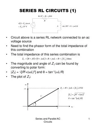
Ch.12 Summary Series RL Circuit Impedance In a series RL circuit, the total impedance is the phasor sum of R and XL. R is plotted along the positive x-axis. XL is plotted along the positive y-axis. Z is the diagonal. It is convenient to reposition the phasors into an impedance triangle.
Ch.12 Summary Series RL Circuit Impedance Sketch the impedance triangle and show the values for R = 1.2 kW and XL = 960 W.
Ch.12 Summary Series RL Circuit Analysis Ohm’s law is applied to series RL circuits using quantities of Z, V, and I. Because I is the same everywhere in a series circuit, you can multiply the impedance phasor values by the circuit current to obtain the voltage phasor values.
Ch.12 Summary Series RL Circuits Analysis Assume the current in the previous example is 10 mA. Sketch the voltage phasors. (The impedance triangle from the previous example is shown for reference.) The voltage phasor diagram can be found using Ohm’s law. Multiply each impedance phasor by 10 mA (as shown below):
Ch.12 Summary Phase Angle Vs. Frequency Phasor diagrams that have reactance phasors can only be drawn for a single frequency because X is a function of frequency. As frequency changes, the impedance triangle for an RL circuit changes (as illustrated here) because XL is directly proportional to f. This determines the frequency response of RL circuits.
Ch.12 Summary Phase Shift A series RL circuit can be used to produce a specific phase lead between an input voltage and an output by taking the output across the inductor. This circuit is a basic high-pass filter, a circuit that passes high frequencies and rejects all others. This filter passes frequencies that are above a specific frequency, called the cutoff frequency.
Ch.12 Summary Phase Shift Reversing the components in the previous circuit produces a circuit that is a basic lag network. This circuit is a low-pass filter, a circuit that passes low frequencies and rejects all others. This filter passes low frequencies up to a frequency called the cutoff frequency.
Ch.12 Summary AC Response of Parallel RL Circuits For parallel circuits, it is useful to review conductance, susceptance and admittance, introduced in Chapter 10. Conductance is the reciprocal of resistance. Inductive susceptance is the reciprocal of inductive reactance. Admittance is the reciprocal of impedance.
Ch.12 Summary AC Response of Parallel RL Circuits In a parallel RL circuit, the admittance phasor is the sum of the conductance and capacitive susceptance phasors: From the diagram, the phase angle is:
Ch.12 Summary AC Response of Parallel RL Circuits Draw the admittance phasor diagram for the circuit below. The magnitudes of conductance, susceptance, and admittance are:
Ch.12 Summary Analysis of Parallel RL Circuits Ohm’s law is applied to parallel RL circuits using quantities of Y, V, and I. Because V is the same across all components in a parallel circuit, you can obtain the current in a given component by simply multiplying the admittance of the component by the voltage as illustrated in the following example.
Ch.12 Summary Analysis of Parallel RL Circuits If the voltage in the previous example is 10 V, sketch the current phasor diagram. The admittance diagram from the previous example is shown for reference. The current phasor diagram can be found from Ohm’s law. Multiply each admittance phasor by 10 V.
Ch.12 Summary Phase Angle of Parallel RL Circuits Notice that the formula for inductive susceptance is the reciprocal of inductive reactance. Thus BL and IL are inversely proportional to f: As frequency increases, BL and IL decrease, so the angle between IR and IS must decrease as well.
Ch.12 Summary Series-Parallel RL Circuits Series-parallel RL circuits are combinations of both series and parallel elements. These circuits can be solved by methods from series and parallel circuits. For example, the components in the green box are in series: The total impedance can be found by converting the parallel components to an equivalent series combination, then adding the result to R1 and XL1 to get the total reactance. The components in the yellow box are in parallel:
Ch.12 Summary The Power Triangle As shown earlier, you can multiply the impedance phasors for a series RL circuit by the current to obtain the voltage phasors. The earlier example is shown below for review: Multiplying each value in the left-hand triangle gives you the corresponding value in the right-hand triangle.
Ch.12 Summary The Power Triangle (Cont’d) x 10 mA = Multiplying the voltage phasors by Irms (10 mA) gives the power triangle values (because P = V I ). Apparent power is the product of the magnitude of the current and magnitude of the voltage and is plotted along the hypotenuse of the power triangle.
Ch.12 Summary Power Factor The power factor was introduced in Chapter 10 and applies to RL circuits (as well as RC circuits). Recall that it is the relationship between the apparent power (in VA) and true power (in W). True power equals the product of Volt-amperes and power factor. Power factor can be determined using: Power factor can vary from 0 (for a purely reactive circuit) to 1 (for a purely resistive circuit).
Ch.12 Summary Apparent Power Apparent power consists of two components; the true power component, which does the work, and a reactive power component, that is simply power shuttled back and forth between source and load. Components such as transformers, motors, and generators are rated in VA rather than watts.
Ch.12 Summary Frequency Response of RL Circuits The response of a series RL circuit is similar to that of a series RC circuit. In the case of the low-pass response shown here, the output is taken across the resistor. Plotting the response:
Ch.12 Summary Frequency Response of RL Circuits Reversing the position of the R and L components produces a high-pass response. In this case, the output is taken across the inductor. Plotting the response:
Ch.12 Summary Key Terms Inductive susceptance (BL) The ability of an inductor to permit current; the reciprocal of inductive reactance, measured in siemens (S).
Ch.12 Summary Quiz 1. If the frequency is increased in a series RL circuit, the phase angle will a. increase b. decrease c. remain unchanged
Ch.12 Summary Quiz 2. If you multiply each of the impedance phasors in a series RL circuit by the current, the result is the a. voltage phasors b. power phasors c. admittance phasors d. none of the above
Ch.12 Summary Quiz 3. For the circuit shown, the output voltage a. is in phase with the input voltage b. leads the input voltage c. lags the input voltage d. leads the resistor voltage Vout Vin
Ch.12 Summary Quiz 4. Which of the equations below can be used to calculate the phase angle in a series RL circuit? a. b. c. both of the above are correct d. none of the above is correct
Ch.12 Summary Quiz 5. In a series RL circuit, if the inductive reactance is equal to the resistance, the source current will lag the source voltage by a. 0o b. 30o c. 45o d. 90o
Ch.12 Summary Quiz 6. Susceptance is the reciprocal of a. resistance b. reactance c. admittance d. impedance
Ch.12 Summary Quiz 7. In a parallel RL circuit, the magnitude of the admittance can be expressed as a. b. c. d.
Ch.12 Summary Quiz 8. If you increase the frequency in a parallel RL circuit, a. the total admittance will increase b. the total current will increase c. both a and b d. none of the above
Ch.12 Summary Quiz 9. The unit used for measuring true power is the a. volt-ampere b. watt c. volt-ampere-reactive (VAR) d. kilowatt-hour
Ch.12 Summary Quiz 10. A power factor of zero implies that the a. circuit is entirely reactive b. reactive and true power are equal c. circuit is entirely resistive d. maximum power is delivered to the load
Ch.12 Summary Answers 1. a 2. a 3. c 4. a 5. c 6. b 7. d 8. d 9. b 10. a