Download
1 / 18
190 likes | 569 Views
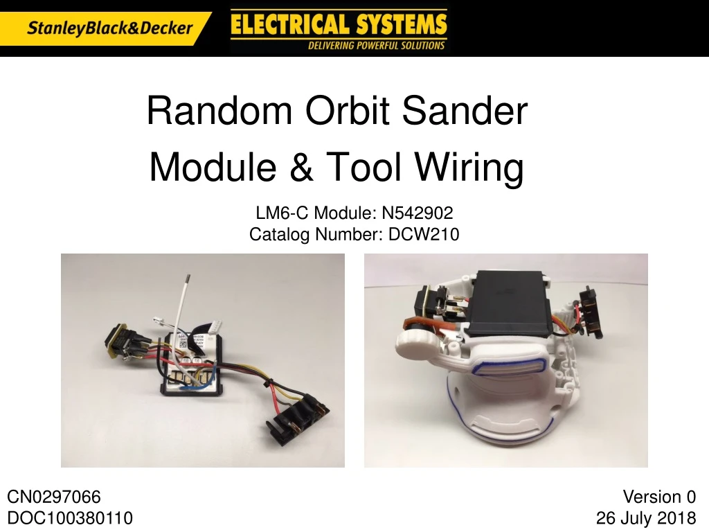
LM6-C Module: N542902 Catalog Number: DCW210. Random Orbit Sander Module & Tool Wiring. CN0297066 DOC100380110. Version 0 26 July 2018. Delta Part Number: ADP-B064-C/CA SBD Part Number: N542902. LM6-C Module Wiring.

E N D
LM6-C Module: N542902 Catalog Number: DCW210 Random Orbit Sander Module & Tool Wiring CN0297066DOC100380110 Version 026 July 2018
Delta Part Number: ADP-B064-C/CA SBD Part Number: N542902 LM6-C Module Wiring *module must have fiber-glass sleeves on B- wire and B+ wire, not shown throughout this presentation
1. Wire grouping and direction from module U, V, W, & Hall wires (UP) Speed dial & switch (LEFT) Terminal block (RIGHT)
2. Terminal block wire routing B+ Red wire Inside motor wires Battery MGM wires Inside motor wires UVW wires Outside of battery/switch wires
3. Switch & speed dial wire routing Speed dial wires Behind & under Hall wires 3x switch wires Behind motor wires
LM6-C Module: N542902 Working Unit: N542085 Tool Wiring & Suggested Assembly
1 – Insert and solder motor wires 3 2 1 Insert W wire, then V wire, and last U wire into terminals and traps
Zip tie assembly Assemble zip tie wrapping U,V,W wires to plastic hook feature Cut remain zip tie material Make sure not to damage insulation wires at cutting process
2 – Connect Hall wire harness Connect harness & strain relief
8 – Switch, speed dial, & terminalsassembled into housings Switch mounting panel held by ribs on both sides Terminal block Speed dial (wheel not shown)
9 – Confirm internal wire routing Confirm phase wires are BEHIND terminal block & switch wires
10 – Terminal block wires Terminal block wires must be clear of housing edge – visually confirm before assembling top cap Zip tie may help pull wires into housing


