Download
1 / 17
170 likes | 307 Views
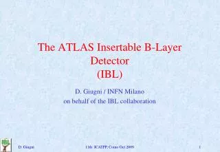
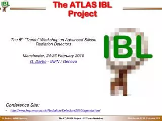
Marius Wensing on behalf of the ATLAS IBL DAQ group TIPP2014, Amsterdam, 2nd-6th of June 2014. Firmware development and testing of the ATLAS IBL Back-Of-Crate card. ATLAS Pixel Detector. ATLAS is one of the four big experiments at the LHC at CERN.

E N D
Marius Wensing on behalf ofthe ATLAS IBL DAQ group TIPP2014, Amsterdam, 2nd-6th of June 2014 Firmware development and testing of the ATLAS IBL Back-Of-Crate card
ATLAS Pixel Detector • ATLAS is one of the four big experiments at the LHC at CERN. • Pixel Detector is the innermost detector with 80 mio. pixels in 3 barrel-layers and 3 disks per side. • Currently it is being updated with a new innermost layer (Insertable B-Layer) with additional 12 mio. pixels. Pictures: CERN
Insertable B-Layer • Bandwidth permodule increasesby a factor of 2 • IBL stave: • 12 planar double-chip modules • 8 3D single-chip modules • 32 front-end chips per stave • New readout hardwareto cope with higher bandwidth → Details in Cécile Lapoire’s IBL overview talk
IBL readoutsystem • IBL readout isbased on thecurrent Pixeldetector readout. • Parts of the Off-Detector-system: • ROD: Read-Out-Driver (→ details in next talk by Shaw-Pin Chen) • BOC: Back-Of-Crate card • TIM: Timing, Trigger, Control Interface Module • SBC: VME Single-Board-Computer
ATLAS IBL BOC card • BOC card is responsible for signal processing of data to and from the detector as well as monitoring the signalquality and providing the link to thehigher level readout. • Components: • 1 BOC Control FPGA (BCF, Spartan-6) • 2 BOC Main FPGAs (BMF, Spartan-6)for signal processing • Gigabit Ethernet,VME • Optics: SNAP12, QSFP • Optical interfaces: • Downlink: 16 channels (BPM, 40 Mbit/s) • Uplink: 32 channels (8b10b, 160 Mbit/s) • Higher level readout: 8x 2 Gbit/s SLINK
Requirements: • BPM encoding of clock and data into single data stream • Adjustment of the detector timing in steps of ~100 ps Signal processing • Downlink (tothedetector): • Uplink (fromthedetector): • Requirements: • Sending clock phase is unknown • 160 Mbit/s data stream • 8b10b encoded data
Implementation ofthe Fine Delay block • Adjustmentofthedetectortimingisneededtocompensatetheeffectoffibrelengthsanddistancestotheinteractionpoint. • Requirements: • Delay in stepsofaround 100 ps • Dutycycleshould not exceed (50±2)%toensure proper optoboardoperation. • Different approachesweretakenintoaccount: • Externaldelaychips • Propagation delays in-sidethe FPGA • IODELAY2 primitive Picture: Xilinx
Implementation of Fine Delay with IODELAY2 • Spartan-6 has different configurationoptionsforthe IODELAY primitive: • Fixed outputdelay • Fixed/variable inputdelay • Variable outputdelayrequiresworkaround: • Variable inputdelayofunused I/Owill berouted back totheoutput. • High distortionofthedutycycle. • Additional I/O portsareneeded. Picture: Xilinx
Partial reconfigurationapproach • Fixed outputdelayconfigurationcanbechangedbyaccessingtheinternalconfigurationmemoryoverthe ICAP interface. • FPGAs havethepossibilityofpartial reconfiguration. • Idea: After thesynthesis differentconfigurationfiles will begeneratedbychangingthedelaysettingper channel. • A differential (partial) configurationisgeneratedandputintotheFPGA‘sconfigurationmemory. • Possibilitytochangethedelayduringoperationofthesystem.
Resultsfromthedelaytest • Partial reconfigurationofthe IODELAY2 givesexcellentresults in termoflinearityandduty-cycle. Mean: 34.93 ps / SettingRMS: 0.7 ps / Setting
Front-End Emulator • Front-End Emulator was implementedintothe BOC firmware. • Emulator canbeusedfordebuggingthefullreadoutchainduring ATLAS milestoneruns, evenwhenthedetectoris not yetavailableforoperation. • Features: • Global registerread/write • ConfigurableChip ID • Manual/Random hitinjection • Configurablenumberofrandomhits per trigger
Front-End Emulator: Hit occupancymeasurement → Emulator provides uniform distribution of hits!
Summary • The upgrade ofthepixeldetectorneedsnew FPGA-basedreadoutelectronicsprocessing 32 channels at a total data rate of 5 Gbit/s. • Timing ofthedetectoriscontrolledby FPGA internalresources. • New methodofadaptingthefinedelayusing partial reconfigurationshows a veryhomogeniousdistributionofthedelay per setting. • Front-end emulatormakesdebuggingofthefullreadoutchainmucheasier. • Productiontestensuresthegoodqualityofdeliveredcards.
IBL BOC Block diagram ROS VME backplane Detector ROS Detector
BOC productiontestoverview • After receptionfromthemanufacturer a testprocedureisperformed on all cards: • Optical inspection • Electricaltestand FPGA programming • Optical tests (loopback, signalintegrity) • Coarseandfinedelaycalibration • Backplane tests& SLINK test • Software utilityforautomatictestinghasbeendeveloped. So many time-consumingtestscanberunwithoutuserinteraction. • Test results will bedocumented in a database.