Download
1 / 14
140 likes | 315 Views
Distributed 2-stage RTBC LH 2 Pipeline Cryocooler System Design. LEI ZHOU MMAE UCF. Basic features of LH 2 Cryocooler. For prechilling/cooling of the transportation pipeline of liquid Hydrogen Capable of removing heat at 19K

E N D
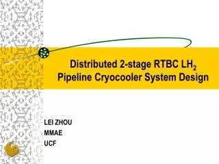
Distributed 2-stage RTBC LH2 Pipeline Cryocooler System Design LEI ZHOU MMAE UCF
Basic features of LH2 Cryocooler • For prechilling/cooling of the transportation pipeline of liquid Hydrogen • Capable of removing heat at 19K • Distributed mid-size cryocoolers are the best solution for the long LH2 pipeline
Distributed RTBC cryocooler • Reverse Turbo-Brayton cryocooler has higher efficiency than JT cryocooler • With oil-free design, Turbo-compressor/expander has high reliability • Distributed mid-size cryocoolers can be • Easy installable and manageable • Expandable • Redundant • Efficient
Cryocooler cooling power analysis How much heat should be removed? How much cooling power needed to chill down a 50-ft-long-pipe in 24 hours The Invar LH2 pipeline should be chilled down from 310K to 19K. Size: 10-inch diameter D, 8 mm pipe wall thickness th (estimated) Q=1908 kJ /ft P=Q*50/24*3600=1104W
2-stage RTBC: — a way to reduce chilling time • Chill down with top cycle to 80K • Switch the top cycle flow to cool the bottom cycle, use bottom cycle to chill down to 19K • Total time: 7.4 hr • Chill down with the both stages simultaneously to 19K • Total time: 24.2 hr
Top cycle Flow switch Inter-heat exchanger / bottom cycle Cooling load interface 2-stage RTBC cryocooler
Top cycle Flow switch Inter-heat exchanger / bottom cycle Cooling load interface 2-stage RTBC cryocooler:—working mode1 CLI temperature: 80K Cooling power: 9.95 kW ; Cooling time: 2.2 hr
Top cycle Flow switch Inter-heat exchanger / bottom cycle Cooling load interface 2-stage RTBC cryocooler:—working mode2 CLI temperature: 19K Cooling power: 1.1 kW ; Cooling time: 5.2 hr
Qrej Qrej Turboalternator Intercooler DC Reg-ulator/ Power Supply DC Power Supply External HX Recuperator Motor/ 2 Stage intercooled compressor Motor/ 2 Stage intercooled compressor Recuperator Turbo expander/brake Load Interface System configuration
System Optimization • System requirements: • Cooling temperature: 19K • Cooling power: 1100 W • Working temperature: 310 K • Optimizable parameters: • Bottom Cycle pressure ratio: Pr
Ti=80K COP vs. Pr
Spec. of Components • Top cycle: • Compressor: centrifugal 2-stage intercooled, Pr=2.42 • Motor: 85 kW, efficiency>=0.85 • Heat regenerator: 0.987 effectiveness, 121 kW • Turbine: turbo-expander with generator, 11.2 kW • Bottom cycle: • Compressor: centrifugal 2-stage intercooled, Pr=3 • Motor: 15 kW, efficiency>=0.85 • Heat regenerator: 0.96 effectiveness, 11.7 kW • Turbine: turbo-expander with gas brake, 1.5 kW
Conclusions • With system optimization, the proposed system can have a COP around 0.01 W/W • Cooling power analysis shows that the cryocooler system is a mid-size system which is capable of chill down a 50-ft transfer line to 19K in about 8 hours