The n- 3 He Parity Violation Experiment
200 likes | 389 Views
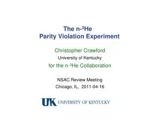
The n- 3 He Parity Violation Experiment. Christopher Crawford University of Kentucky for the n- 3 He Collaboration NSAC Review Meeting Chicago, IL, 2011-04-16. Outline. Scientific Motivation Reaction and PV observable Theoretical calculations Previous experiment Experimental setup

The n- 3 He Parity Violation Experiment
E N D
Presentation Transcript
The n-3He Parity Violation Experiment Christopher Crawford University of Kentucky for the n-3He Collaboration NSAC Review Meeting Chicago, IL, 2011-04-16
Outline • Scientific Motivation • Reaction and PV observable • Theoretical calculations • Previous experiment • Experimental setup • Transverse RF spin rotator • 3He target / ion chamber • Sensitivity • Statistical sensitivity, simulations • Systematic errors • Alignment scheme • Management plan • Work packages, level of effort • Installation at FnPB • Projected schedule
n-3He PV Asymmetry 20.578 19.815 Tilley, Weller, Hale, Nucl. Phys. A541, 1 (1992) p S(I): θ n 3He 3H PV observables: ~ kn very small for low-energy neutrons - the same asymmetry - must discriminate between back-to-back proton-triton • sensitive to I=0 and I=1 couplings • PV A ~ 1.1 x 10⁻⁷ (Viviani) • PC A ~ 1.7 x 10⁻⁶ (Hale) GOAL: dA = 1.3 x 10⁻⁸
Theoretical calculations • Gerry Hale (LANL) PC Ay(90) = -1.7 +/- 0.3 x 10⁻⁶ • R matrix calculation of PC asymmetry,nuclear structure , and resonance properties • Vladimir Gudkov (USC) PV A = -(1 – 4) x10-7 • PV reaction theory • Gudkov, PRC 82, 065502 (2010) • Michele Viviani et al. (INFN Pisa) PV A = -1.14 x 10⁻⁷ • Full 4-body calc. of strong scattering wave functions Jπ = 0+, 0-, 1+, 1- • Eval. of weak <J-|VPV|J+> matrix elements in terms of DDH potential • Work in progress on calculation of EFT low energy coefficients • Viviani, Schiavilla, Girlanda, Kievsky, Marcucci, PRC 82, 044001 (2010)
n-3He PV experiment in 1981 Neutron flux: 6 x 10⁷ n/s Polarization: 97% (transverse) PV: Ap = 0.38 ± 0.49 x 10⁻⁶ PC: Ap = -0.34 ± 0.57 x 10⁻⁶ JETP Lett, 33, 411 (1981)
Experimental setup longitudinal holding field – suppressed PC asymmetry RF spin flipper – negligible spin-dependent neutron velocity 3He ion chamber – both target and detector record ionization signal in each wire; spin asymmetry -> Ap supermirror bender polarizer (transverse) 10 Gauss solenoid shim coils (not shown) FnPB cold neutron guide 3He Beam Monitor transition field (not shown) RF spinrotator 3He target / ion chamber n-3He (new equipment) FNPB (already exists)
Transverse RF spin rotator • Resonant RF spin rotator • P-N Seo et al., Phys. Rev. S.T. Accel. Beam 11, 084701 (2008) • Properties suitable for n-3He expt. • Transverse horizontal RF B-field • Longitudinal or transverse flipping • No fringe field - 100% efficiency • Doesn’t affect neutron velocity • Compact geometry • Matched to the driver electronicsof the NPDGamma spin flipper • Construction • Development in parallel with similar design for nEDM neutron guide field • Few-winding prototype built at Uky currently being tested • Full size RFSF to be built this year field lines end cap windings
Detector / Ion Chamber The chamber design was finished in 2010 and the completed chamber was delivered to U. of Manitoba in the Fall of 2010. The chamber has: 4 data ports for up to 200 readout channels. 2 HV ports 2 gas line ports 12 inch Conflat aluminum windows (0.9 mm thick). The chamber is made completely from aluminum except for the knife edges.
Preliminary wire frame and readout design The chamber is large enough to completely cover the SNS beam profile, even without collimation. We are currently optimizing the competing issues of frame size and wire spacing vs. frame rigidity and material cost. Macor would be best, but very expensive. Other possibilities include Peek (pure too soft), carbon or glass filled peek.
Preliminary wire frame and readout design Current options being explored: 1) 6.4 mm thick frames with 18 HV and 17 signal wires (alternating). 8 wires per signal frame9 wires per HV frame~ 2 cm wire spacing 136 signal wires 2) 4.8 mm thick frames with 23 HV and 22 signal wires.10 wires per signal frame~1.5 cm wire spacing 220 signal wires total (omit the last two frames). Also shown are initial ideas for readout and HV distribution boards above and below to frames.
MC Simulations • Two independent simulations: • a code based on GEANT4 • a stand-alone code including wire correlations • Ionization at each wire plane averaged over: • neutron beam phase space • capture distribution • ionization distribution (z) • uniform distribution of proton angles cos n¢kp/kp • Used to calculate detector efficiency (effective statistics / neutron flux)
MC Simulations – Results • N = 2.2x10¹⁰ n/s flux (chopped) x 107 s (4 full months @ 1.4 MW)P = 96.2% neutron polarizationd = 6 detector efficiency • Majority of neutron captures occur at the very front of chamber • Self-normalization of beam fluctuations • Reduction in sensitivity to A
Backgrounds Neutron flux vs. Wavelength • Wraparound neutronsBACKGROUND: < 0.02%, • Compton electrons from Gammas • 10% gammas/neutron from SNS • Conservative, assuming E=.5 MeV • 2.4% probability of Compton scattering from Al window • 10% ionization current from e- vs. p+ BACKGROUND: < 0.02%, NO false asymmetry • Betas from Al decay – 2.4 min lifetime • 0.231 b thermal neutron cross section • 0.9 mm thick Al window • 0.25% capture probability; half of decays go through chamber • 10% ionization current from e- vs. p+ BACKGROUND: < 0.015% • Al asymmetry measured for NPDGamma Rob Mahurin, technical note 2009-08-19 Primary window Wrap-around neutrons Neutron & Gamma flux vs. Position gammas x 18 neutrons
Systematics • Beam fluctuations, polarization, RFSF efficiency • Only systematic beam fluctuations contribute (A<<1) • Self-normalizing detector – forward wires sensitive to flux only • Parity allowed asymmetries minimized with longitudinal polarization • Alignment of field, beam, and chamber: 1 mrad achievable • knr ~ 10-5 small for cold neutrons
Alignment procedure • Suppression of 1.7 x 10⁻⁶nuclear PC asymmetry • longitudinal polarizationdoubly suppresses sn . kn x kp • Symmetric detector • Rotate 180 deg about kn during data taking • Align B field to detector within 1 mrad • Vant-Hull and Henrickson windblown generator • Minimize Bx, By by observing eddy currents in generator • Align detector and neutrons to 1 mrad • Perform xy-scans of beam at 2 z-positions before/after target • B4C target in beam with CsI detector, 6Li chopper 6Li Shutter CsI crystal B4C target
Work Packages • Theory - Michele Viviani • MC Simulations - Michael Gericke • Polarimetry - Geoff Greene • Beam Monitor - Rob Mahurin • Alignment - David Bowman • Field Calculation - Septimiu Balascuta • Solenoid / field map - Libertad Baron Palos • Transition, trim coil - Pil-Neyo Seo • RFSF - Chris Crawford • Target / detector - Michael Gericke • Preamps - Michael Gericke • DAQ - Chris Crawford • Analysis - Nadia Fomin • System integration/CAD - Seppo Pentilla • Rad. Shielding / Tritium - John Calarco
Effort Estimate for n-3He Collaborators (Percentage of research time)
Installation at FnPB • Existing equipment: • 3He beam monitor • SM polarizer • Beam position monitor • Radiation shielding • Pb shield walls • Beam Stop • New equipment: • Transition guide field • flight path from SMpol to RFSF (reuse 6Li shielding) • Longitudinal field solenoid mounted on stand • Longitudinal RFSF resonator mounted in solenoid • 3He target/ion chamber mounted in solenoid • Preamps mounted on target • Windblown generator • DAQ: single-board computers + ADC modules + RAID array • Existing electronics: • B-field power supply • RFSF electronics • Trigger electronics • SNS / chopper readout • Fluxgate magnetometers • Computer network
July 2012 Stage stand, solenoid,RFSF, Target/Ion Chamberin nEDM building Dec 2012 Installation at FnPB Field map at FnPB Feb 2013 Beam axis scans 3He Polarimetry Apr – Dec 2013 3He data-taking Jan – Dec 2011 Construction and field mapping of solenoid at UNAM Construction and testing of RFSF resonator at UKy Assembly of 3He ion chamber at Univ. Manitoba DAQ electronics and software at UKy / UTK / ORNL Jan – May 2012 test RFSF, 3He chamber, and DAQ at HFIR Projected schedule Offsite SNS Beam time request: 5000 hrs.
Conclusion • Theoretical progress • Full 4-body calculation published, EFT calculation under way • Test of consistency of DDH or EFT within few-body systems • Experimental progress • Prototype RFSF resonator designed and built • Target chamber delivered, instrumentation under way • Sensitivity • Statistics: ±A = 1.3 x 10⁻⁸, low background levels • Systematic effects suppressed with longitudinal polarization • Will be ready to commission and run after NPDGamma