Download
1 / 6
60 likes | 175 Views
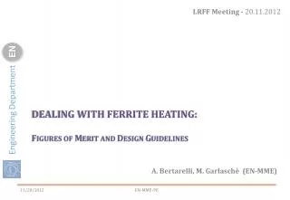
LRFF Meeting - 20.11.2012. Dealing with ferrite heating: F igures OF M erit And d esign g uidelines. A. Bertarelli, M. Garlaschè (EN-MME). Analysis introduction. The goal: Determine figures of merit for maximum RF induced power on ferrite before T CURIE is reached.

E N D
LRFF Meeting - 20.11.2012 Dealing with ferrite heating:Figures OF Merit And design guidelines A. Bertarelli, M. Garlaschè (EN-MME) EN-MME-PE
Analysis introduction The goal: Determine figures of merit for maximum RF induced power on ferrite before TCURIE is reached The assumptions: Steady-state regime and uniform ferrite temperature distribution (regardless of actual RF power deposition) Ferrite tile is of arbitrary cross section Ferrite radiates from all sides with equal emissivity (0.8) Completely surrounding heat sink & no intermediate components between ferrite & sink (ferrite view factor equal to 1) 2D simplification of ferrite tile, i.e infinitely long geometry (no end effects) Heat sink with uniform emissivity and temperature EN-MME-PE
Analysis introduction Theequation: Q : [W/m2] radiated heat per ferrite surface unit σB : Stefan-Boltzmann constant T0 : temperature of surrounding heat sink KG : geometry and RF power deposition coefficient(KG≡1 thanks to hyp. # I) Kε: radiation exchange coefficient, function of emissivity and geometry EN-MME-PE
Analysis output Specific power w.r.t. ε0 & KA KA=1 KA=1.6 KA=10 KA=50 KA=100 CASE: εFERRITE =0.8 TCURIE = 150°C T0=22°C (i.e. cooled heat sink) If KA is high no need for very high ε0 Q[W/m2] But ferrite needs to be held, i.e. KA is usually near to one. E.g. TCTP collimator: KA KA~=1.6 ε0[-] EN-MME-PE
Analysis output CASE: εFERRITE =0.8 TCURIE = 150°C T0=22°C (i.e. cooled heat sink) Legenda: Heat evacuation can be handled by radiation only (regardless of geometry) Q[W/m2] Need for ferrite active cooling Output is geometry dependent Critical design zone High KA point of interest Low KA point of interest ε0[-] EN-MME-PE
Analysis output Points of interest obtained for different values of TCURIE Q[W/m2] 2e4 Legenda: Heat evacuation can be handled by radiation only (regardless of geometry) 1.5e4 Need for ferrite active cooling 1e4 Output is geometry dependent 5e3 0 TCURIE[°C] 27 530 150 275 400 EN-MME-PE