Download
1 / 26
260 likes | 370 Views
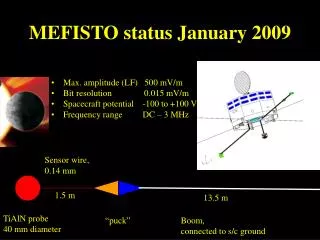
MEFISTO status January 2009. Max. amplitude (LF) 500 mV/m Bit resolution 0.015 mV/m Spacecraft potential -100 to +100 V Frequency range DC – 3 MHz. Sensor wire, 0.14 mm. 1.5 m. 13.5 m. TiAlN probe 40 mm diameter. “puck”.

E N D
MEFISTOstatus January 2009 • Max. amplitude (LF) 500 mV/m • Bit resolution 0.015 mV/m • Spacecraft potential -100 to +100 V • Frequency range DC – 3 MHz Sensor wire, 0.14 mm 1.5 m 13.5 m TiAlN probe 40 mm diameter “puck” Boom, connected to s/c ground
MEFISTO-S (mechanics) • Design and development of flight mechanics is proceeding as planned • Current/recent actions • MEFISTO-S EM finalized • Further testing conducted of deployment mechanism • Refinement of hermal model • No change in resource requirements
MEFISTO-E (electronics) • Design and development of flight electronics is proceeding as planned. New AX EM board ready for testing in mid February. • Current/recent actions • MEFISTO-E EM I/F tests conducted successfully except for the Sorbet I/F (All needed changes implemented) • Boom deployment control successfully tested • A limited EMC test will be performed on the AX EM
MEFISTO-E (electronics) • Resource requirements • Functionality shifted from MDP to MEFISTO may require power increase in MEFISTO (RTAX 250 to 1000) Open work: Frequency response for second EWO filter. Conducted emission (CE) for MEFISTO power supply How to analyze calibration data from 2-700Hz. Storage area for 2 sweeps in the MDP (TBD)
Probe-plasma impedance • Sunlight • Impedance set by photoelectrons • Typical value is 50 MOhm • Current bias is straightforward • Darkness • Impedance set by plasma electrons • Typical value (floating probe) is many GOhm • Bias circuitry needs to be disconnected • Partial eclipse • No obvious best solution
Progress from the last design meeting (Sep 2008) • Since the previous design meeting two interface tests of MEFISTO-E, one in September and one in November, have been performed successfully. Unfortunately, the SORBET test scheduled for December had to be postponed. • MEFISTO-S development is proceeding as planned.
Differences from the nominal plan • A double sweep can be performed inside a spin period.Two sweeps can be uploaded to a FPGA RAM area. • By a single command fourteen ROM preloaded sweeps can be selected and executed. • 5A and A5 have to be sent to the motor control register before a motor command can be executed. • The time command is ignored by MEFISTO. • A command counter in the house keeping can be used for MEFISTO alive check. • The middle frequency overall gain is changed to 6dB. • Two different frequency responses for the middle frequency MEFISTO output can be selected by a relay command. • The output impedance to Sorbet is lowered to 50ohm. • The new EM board can hold an AX1000 or an Actel Flash.
Schedule for MTM, TTM and EM tests • MEFISTO / SORBET interface test. TBS. • The finale EM circuit board assembly will start in mid-January. A complete and fully tested board will be ready for delivery in mid-March. • Prototype preamplifier boards will be ready for testing in the end of January. EMC test result / plan • A limited EMC test (CE) will be performed on the AX EM board. Major A/I status • No vibration or thermal vacuum tests are foreseen on EM board level. • The board level EGSE is fully tested. • The FM EGSE is under development in Oslo and will be ready for use in the end of April.
Major request to System / other subsystems & payloads • Functionality shifted from MDP to MEFISTO may require power increase in MEFISTO (RTAX 250 to 1000) Others • Radiation tests on AD590 and OPA602 (preamplifier located at the top of the wire) using Co60 were performed as a student laboratory work in November. • The OPA602 showed minor changes (0. 1%) of original performance at 180kRad and the AD590 had a linear degradation of maximum -1.4C/10kRad up to 70kRad for the temperature range 0 to 60C. • AM2P can not analyze frequencies below 700Hz and as MEFISTO in orbit calibration starts from 2Hz we need support, preferably from EWO, to cover that gap (2-700Hz). • A safe non volatile storage area for the two MEFISTO up loaded sweep tables is needed in the MDP TBC.
BepiColombo/MMO: PWI / Search Coil MagnetometersReport for MMO Design Meeting #11 [Jan 2009] • Progress from the last design meeting (Sep 2008) • LF-SC • LF-SC in-house crosstalk was examined at Kanazawa (Nov. 10, 2008). • Crosstalk between Bx and By channels had been unacceptably large. • Some of PCB patterns were identified to be vulnerable against noise interference. • A new SC preamplifier “EM2” is designed (to be manufactured by Feb. 2009). • Some part of the preamplifier circuit will be modified for better performance. • PCB patterning will be improved so as to avoid the in-house crosstalk. • DB-SC • 3D+ preamplifier has been fully manufactured, delivered and tested alone and together with LF-SC preamplifier at Kanazawa. PWI/SCM
SCM EM Integration Test • DB/LF-SC EM integration test was performed at Kanazawa (Nov. 11-15, 2008). • Electrical and mechanical I/F (DB-SC, LF-SC, and MAST) was confirmed. • Electrical performance was confirmed to be almost compliant with specification. Some problems were spotted, including the non-negligible crosstalk from Bz(LF) to Bx/By. • Tri-axial sensor configuration on the MAST top plate, covered with MLI (Boots) was tested. No serious influence was found on the sensor performance. • Electrical performance will be more accurately calibrated at Chambon la Foret, France (Mar. 2009). • DB(LF)-SC and EWO-B I/F test was performed at Kyoto (Nov. 17, 2008). • Electrical performance was confirmed to be almost compliant with specification. • Crosstalk from DB-SC (Bz-LF) to LF-SC (Bx/By) was examined at Kyoto (Nov. 18, 2008). • Such a crosstalk was found to originate from the coupling between the PCB signal patterns on the preamplifier. PCB patterning and structure will be improved on the “EM2” preamplifier under development (by Feb. 2009). • DB-SC (HF) and SORBET I/F test was performed at Meudon la Foret. • Power consumption, dynamic, transfer function, calibration function, and noise (Dec. 04, 2008). PWI/SCM
(2) Problems / Differences from the nominal plan • LF-SC EM sensors - Previous candidate for the core adhesive has failed to pass the outgas qualification test at Tsukuba. Another candidate has been prepared and will be tested soon, again at Tsukuba (January? 2009). • LF-SC EM preamplifier - Problems spotted during SCM EM tests should be solved with “EM2” (Mar. 2009). - Crosstalk among Bx, By and Bz. - Better electrical performance. • DB-SC preamplifier Transfer function resonance on LF output is under examination. • Others - Whiskers on Pb-free JFET. - How to evaluate vertical antenna effect? (SC with sensitivity to E-field) - FM procurement of 10uF capacitors. PWI/SCM
(3) Schedule for EM tests • EM delivery completed: EM LF-SC sensors and preamplifier (August, 2008) EM DB-SC sensor (July, 2008), preamplifier (October, 2008) • EM test (2008) August 27-29: LF-SC component test (Kanazawa) September 04: LF-SC and EWO-B I/F test (Kyoto) October 20-29: DB-SC component test (CETP) November 10: LF-SC crosstalk test (Kanazawa) 11-15: DB/LF-SC EM integration test (Kanazawa) 17: DB(LF)-SC and EWO-B I/F test (Kyoto) 18: DB/LF-SC crosstalk test (Kyoto) December 04: DB-SC and SORBET I/F test (Meudon) • EM development and test schedule (2009) January-February: LF-SC-Pre “EM2” development & manufacture March: LF-SC “EM2” delivery & component test (Kanazawa) DB/LF-SC Full calibration test (Chambon la Foret) April: PWI EM integration test (Kyoto) May(TBC): Thermal test (ISAS), Vibration test (NIPPI) PWI/SCM
(4) EMC test result / plan (*1) e.g. EM, BBM, equivalent model (*2) DCB = DC and low-frequency Magnetic field / CE = Conductive Emission / RE = Radiation Emission (*3) ISAS, Kyoto Univ. (RE and CE), Kanazawa Univ. (RE04), or other Subsystem/Payload name 14
(5) Major A/I status • Re-evaluation of grounding concept of MLI and harness shield : - Configuration: MAST Boots + MLI -> MMO body, Harness shield -> COM2 - Will be examined again at the full calibration test (Chambon la Foret, March 2009). • Maximum allowable level of magnetic field strength at each frequency : - Computation has been done. Now confirming the result. • Thermal design of SC-Pre with temperature tolerance (+95degC) : - Will be evaluated at the EM thermal cycling test (May? 2009). [LF-SC] • Adjustment of LF-SC calibration levels : - Preliminary adjustment has been done. - Will be confirmed at the full calibration test (Chambon la Foret, March 2009). • Outgas measurement for LF-SC sensor materials (core adhesive) : - Previous adhesive candidate failed. Another candidate will be tested soon (January? 2009). [DB-SC] • Measurement of DB-SC core Curie temperature : - New magnetic material has been fabricated and delivered. Curie temperature of composition n°8 is higher to 200°C (cf. graph) • DB-SC mechanical design update : Environmental tests will arbitrate (date TBD). PWI/SCM
(6) Major request to System / other subsystems & payloads • We would like to confirm the magnetic field noise levels produced by the vibration test facilities at ISAS/ESTEC, as too high voltages induced at each search coil sensor output could be harmful for its preamplifiers. • We would like to confirm the temperature range at both sensors and preamplifier level. • We would like vibration load specification at sensors level. (7) Others PWI/SCM
(1) Progress from the last design meeting (Sept. 2009) EM developments • Unit tests • SORBET has been tested and functionally validated • Thermal testing to be done in the range -25 degC to +75 degC • Interfaces verification tests • EWO and WPT preamps: Done at RISH in Oct. 2008 • MDP: Done at ISAS in Nov. 2008 and Jan. 2008 • HF-SC: Done at LESIA in Dec. 2008 • MEFISTO: To be done • EM updates • Daughter board will be updated for integration in PME chassis – April 2009 • New EM version planned for environmental testing – June 2009 ASIC developments • ASIC design • TNR_ASIC fully validated • HFR_ASIC need to be optimized – New version for 2Q/2009 • ASIC qualification • Specification (based on the ESCC-9000) for packaging and qualification • 2 subcontractors contacted PWI/SORBET
(1) Progress from the last design meeting (Sept. 2009) FPGA developments • Improvement and optimization of the FPGA design • Normalization of the VHDL code • Improvement of the design reliability and the speed margin • Reduction of the occupation area (from 95% to 85%) • SpaceWire IP updated with its latest version (v1_01e11) • Flight configuration, including the LEON3-FT IP, is on-going • FPGA without socket(AX1000-1CQ352M) – April 2009 EGSE • H/W module is under design – April 2009 • Functionalities and interfaces definition • Study of EMC/EMI cleanliness • Design is in progress • S/W tools • Main functions almost finished (users interface, stimuli and data management) PWI/SORBET
(2) Problems / Differences from the nominal plan • None (3) Schedule for MTM, TTM and EM tests • PME integration in April 2009 • Daughter board and FPGA updates • Environmental testing in June 2009 • Mother board and HFR ASIC updates (4) Major A/I status • EM updates • 2nd EM version – Schematic and PCB • FPGA in its flight configuration • Modification of the HFR ASIC • EGSE H/W design • ASIC qualification (5) Major request to System / other subsystems & payloads • None (6) Others • None PWI/SORBET
BepiColombo/MMO: PWI / EWOReport for MMO Design Meeting #11 [Jan 2009] • Progress from the last design meeting (Sep 2008) • Analogue I/F tests with other PWI components (at Kyoto University) • EWO-MEFISTO-AM2P (Sept. 22 – 26, 2008) • Frequency response (MEFISTO-S-MEFISTO-E-EWO) • Noise level measurement (MEFISTO-S-MEFISTO-E-EWO) • Bias sweep control by the EWO-FPGA • LVDS I/F check between the AM2P and EWO-FPGA • Check of the interface of the AM2P synthesizer as the calibration source of the EWO • AM2P-S – MEFISTO-E – EWO I/F test • Mechanical fitness check of the MEFISTO-E and AM2P-E boards to the PME chassis • EWO-SORBET (Oct. 14-16, 2008) • SORBET-EWO signal level and noise level check • WPT-Pre-EWO-SORBET signal level and noise level check • Mechanical fitness check of the SORBET board to the PME chassis • EWO-SCM(Nov. 17-Nov. 18, 2008) • Frequency response(SCM-EWO) • Check of the crosstalk (SCM-EWO) • Check of the noise level (SCM-EWO) PWI/EWO
BepiColombo/MMO: PWI / EWOReport for MMO Design Meeting #11 [Jan 2009] • Progress from the last design meeting (Sep 2008) • Digital I/F tests with other PME components • EWO-MDP I/F tests (Nov. 11-No. 14, 2008) • Commands and HK status checks • Data handling check based on the SpW interface • EWO-FPGA tests (Nov. 26-Nov. 28, 2008) • EWO-GSE check • Check of the digital waveform data of the EWO using the packet data • Check of the noise level of the EWO using the packet data • Check of the digital filter function implemented in the EWO-FPGA • Check of the bias sweep control • EWO-FPGA-AM2P I/F tests(Dec. 1-Dec. 3, 2008) • Check of the timing of control and data acquisition between EWO-FPGA and AM2P • Digital data collection of the AM2P synthesizer output through the EWO • Digital data collection of the AM2P synthesizer in the onboard calibration sequence • EWO-EFD-MGF-I synchronization test (Dec. 15, 2008) PWI/EWO
(2) Problems / Differences from the nominal plan • EWO-EFD • Re-adjustment of the bias circuit gain is necessary. • EWO-OFA/WFC • Crosstalk level of the EX1-EX2 channels should be improved. • Digital waveforms of the OFA/WFC(B) are distorted due to the effect of the analogue switch timing. • EWO-MEFISTO • The gain setting of EWO-OFA/WFC should be reconsidered based on the characteristics of the MEFISTO-S frequency response. • EWO-AM2P • Some modifications are needed in the logic between the EWO and AM2P in order to define the precise start timing of the AM2P synthesizer in the observed waveforms. • The onboard calibration sequence using the AM2P synthesizer should be re-considered in order to optimize the onboard data processing. • EWO-FPGA • The digital filters of the EWO-EFD and EWO(B) has not functioned properly. • Several logic errors found in the unit level have been found. PWI/EWO
(3) Schedule for EM tests • EM delivery completed: The final EM of the EWO will be delivered in the end of March, 2009. • EM development and test schedule (2009) April: PME EM integration test (Kyoto) May: C & DH I/F test #2 June: Environment tests in the PME level PWI/EWO
(4) EMC test result / plan (*1) e.g. EM, BBM, equivalent model (*2) DCB = DC and low-frequency Magnetic field / CE = Conductive Emission / RE = Radiation Emission (*3) ISAS, Kyoto Univ. (RE and CE), Kanazawa Univ. (RE04), or other PWI/EWO 24
(5) Major A/I status • The OFA/WFC gain allocation is needed to be fixed. • The onboard calibration sequence should be designed considering the onboard data processing. The above A/I will be discussed in the PWI meeting on January 7th . • The radiation tests of the FET of the WPT-Pre will be performed as soon as possible consulting the delivery schedule of the FET used for the FM. PWI/EWO
(6) Major request to System / other subsystems & payloads None (7) Others None PWI/EWO