Download
1 / 20
200 likes | 351 Views
Improving the Routing and Addressing of IP. Ford, Rekhter, and Braun IEEE Network Magazine May 1993 George Lee. Abstract. The current routing and addressing structure dose not adequately scale to meet the needs generated by the accelerated growth of the Internet.

E N D
Improving the Routing and Addressing of IP Ford, Rekhter, and Braun IEEE Network Magazine May 1993 George Lee
Abstract • The current routing and addressing structuredose not adequately scale to meet the needs generated by the accelerated growth of the Internet. • This article introduces hierarchy into the interdomain routing system. • Routing on IP address prefixes • Summarization – to aggregate multiple routing entries • Renumbering when site moving • To change host addresses within a site to their new network service provider • Advantages: • reduction in routing overhead 2
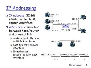
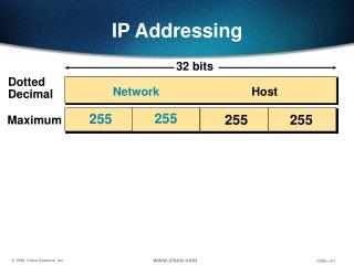
IP Address Structure • 32-bit long address represented as “dotted quads” • Each octet is represented as a decimal number, separated by dots • Consisting of a network address field and a host identifier field • Threeclassesofunicastaddresses: 3
Subnetting with a subnet mask • represented in dotted quad form • 1’s: network address • 0’s: host identifier • Subnet information is not globally distributed. 4
Routing • IP routing domain • A collection of hosts and routers under the control of a single administrative entity using a common routing system • Intradomain Routing • Interior Routing Protocols (IGPs) • OSPF (Open Shortest Path First) • IGRP (Interior Gateway Routing Protocol) • RIP (Routing Information Protocol) • IS-IS (Intermediate-System, Intermediate-System) • Interdomain Routing • Exterior Routing Protocols (EGPs) • EGP (Exterior Routing Protocol) • BGP (Border Gateway Protocol) 5
The relationship between Intradomain and Interdomain routing can be illustrated by the NSFNET: • Hierarchical Architecture • Sites IGP EGP • Regional Networks IGP EGP • NSFNET Backbone EGP • Using IGP: • Within Sites • Within Regional Networks • Using EGP: • Between Sites and Regional Networks • Between Sites and NSFNET Backbone • Between Regional Networks and NSFNET Backbone 6
EGP IGP 7
Hierarchical structure of NSFNET • Simplifying the routing: • Sites only need to maintain routing information for their networks and a default route to the regional network • Regional networks only need to maintain routes to their member sites and a default route to the NSFNET backbone • NSFNET backbone only need to maintain routes to their member sites and regional networks • Five top-level routing domains: • NSFNET Backbone • Commercial Internet eXchange (CIX) • NASA Science Internet (NSI) • SprintLink • European IP Backbone (EBONE) 8
Current Status of Routing • The current routing of flat interdomain routing by network number dose not scale adequately in light of the Internet’s continued growth. • Memory and computational overhead for routing information • Bandwidth for routing information distribution • Stability of distributed routing computations • Class B networks only advertise a single routing entry (214). But each Class C network will require a separate route entry (222) – resulting in even faster growth of Internet Interdomain routing system. 9
Hierarchical routing has desirable scalable properties, but requires the use of hierarchical abstractions of network addresses. • Router software will need to be changed, but these changes can be made transparent to host software. 10
Routing on IP Address Prefixes • Classless Interdomain Rouging (CIDR) • IP Address Prefixes (up to 32 bits) • Tuple representation:<IP network address, bit mask> • bit mask • specifying contiguousleading address bits that are significant to Internet routing (similar to subnet mask) • represented in dotted quad form • Example: <193.128.0.0, 255.128.0.0> • 9-bit IP prefixed(a leading one bit and followed by eight zeros) • 100000000 - 11000001.10000000.00000000.00000000 • Significant network field: 11000001.1 11
Hierarchical Abstraction can be provided by the Summarization • A pair of prefixes of length N can be summarized to a single prefix of length N-1 if the prefixes have the first N-1 bits in common. • Example: 1010 and 1011 → 101 • Summarization can be repeatedly applied to aggregate multiple routing entries into a single entry∴ Minimizing the number of routes distributed ∴ Scaling better 12
OSPF, RIP-2, and BGP-4 can carry 32-bit prefix bit masks. • CIDR was Initially proposed for Class C address, but it can also be used for Class A and B. • The current CIDR specifies three-level architecture, however, additional levels can be added if needed. • At the site level • At the network service providers • At continental boundaries • Service providers may operate on several regions, but they should obtain addresses out of the the continental regions they serve – to maximize the summarization capability for each region. 13
The Best Match is the Longest • The destination address is matched with the candidate prefixes in the routing table. • The list of prefixes is sorted by length and searched in the descending order. • Example: (See the picture on the next page) • Provider A: <198.1.0.0, 255.255.0.0>Site S: <198.1.8.0, 255.255.248.0> • ∵Summarization ∴ A advertises <198.1.0.0, 255.255.0.0> • Provider B: <199.3.0.0, 255.255.0.0>Site T: <199.3.128.0, 255.255.128.0> • ∵Summarization ∴ B advertises <199.3.0.0, 255.255.0.0> • Suppose that Site S switches to provider B • ∴ B advertises <199.3.0.0, 255.255.0.0> 15
∵Summarization∴ Provider A advertises <198.1.0.0, 255.255.0.0>∴ Provider B: advertises <199.3.0.0, 255.255.0.0> • Routing tables are sorted by prefix length • When Site S switches to provider B,B adds one entry for S • If B needs to forward packet to Site S, it will use the longest matching prefix S instead of prefix A. 16
Names, Not Addresses, Are Permanent • Renumbering • When a site switches to a new service provider, but keeps its old address, additional routing prefix are advertised. • But, if hosts addresses within that site are changed to related prefix of the new provider, additional routing overhead is reduced. • However, there is not an automatic, easy-to-use method for changing host addresses within a site. 17
1) S’s prefix is part of A’s prefix • 2) S switches to provider Band S’s prefix is till part of A’s prefix • 3) S renumbers into B’s prefix, Interdomain routing tables shrink 18
Utilization of the IP Address Space • Summarization • A site with contiguous Class C addresses can summarize to a single routing advertisement • Variable length subnetting • A site can split a Class B network into smaller “area” using prefixes of different length, thus avoiding the waste on IP addresses 19
Conclusion • To use IP prefixes instead of IP network addresses • Scale the routing system • Reduce the rate of IP address consumption 20