Download

1 / 35
350 likes | 366 Views
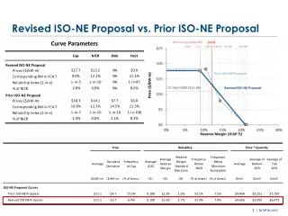
Working towards a revised MPD standard (ISO 13473-1). a sneak-peek on the current mind set. Bo Söderling; LMI Technologies Ltd. A look back. 1985-1990 – laser sensors are established as THE TOOL for road measurements.

E N D
Working towards a revised MPD standard (ISO 13473-1) a sneak-peek on the current mind set Bo Söderling; LMI Technologies Ltd
A look back.... 1985-1990 – laser sensors are established as THE TOOL for road measurements. 1988 – Selcom introduces the first generation of laser sensors dedicated to texture measurements. 1997 – ISO 13473-1 is issued as a result of research and industry requirements to provide continuation and improvement from previous generation technologies and comparability. 1997-2011 – Industry demands drives technology towards higher sampling rates, larger MR’s and smaller laser spots. 2009 – Selcom (now LMI Technologies) are invited to contribute as observers at WG39 to the revision of ISO 13473-1. 2009 - 2011– LMI participates in quarterly WG39 meetings to review the standard, identify weak points and establish improvements.
And how do we get there?MSD/MPD; the process to get to the numbers • MSD calculation • Slope suppression • 2 Peaks & average of segment • MSD = average of peaks – average of segment • Data collection & preprocessing • Invalid points & interpolation • Re-sampling to spatial domain • Sharpness normalization (low pass filter) • Sensor • Basic model (Optocator 2008, 2207) • Sample rate (32, 62,5, 78 kHz) • Measurement Range (64, 128, 155, 180mm)
Sensor • Basic type (Optocator 2008, 2207) • Sample rate (32, 62,5, 78 kHz) • Measurement Range (64, 128, 155, 180mm)
From the sensor stand-point... Defined laser spots Faster sampling Less weight & size The task: measure profiles to enable MPD data Allow more vertical movement Higher precision Measure fresh asphalts Accurate detection of Invalid conditions
Sensor optimization and verification ”The LMI approach” • Establish methods to reproduce road sample discs with controlled properties. • Develop a test system and software capable of evaluating MSD,MPD, ETD, RMS. • Enable real road data collection from representative LMI ”test tracks”. • Investigate the influence from various types of profile filtering. • Benchmark, optimize and qualify products on an individual level by using results from all above. • Improve designs based on experience from all above.
Sample disk reproduction procedure Clones with varying properties Original Silicone mold
Test tracks of varying character Site 1- MPD: 0,8 mm Site 2 – MPD: 1,45 mm
New ”High Power/Low Noise” option • Higher power laser diodes enable higher data precision and reduced noise. • Similar performance at 3 x speed. 32 kHz sensor @ 20 kph 78 kHz High Power/Low Noise sensor @ 60 kph
WG 39 proposes: To be continued......
Data collection & preprocessing • Invalid points & interpolation • Re-sampling to spatial domain • Sharpness normalization (low pass filter)
Optical phenomena may blind the sensor • occlussions • ”impossible” slopes • fresh asphalt Profile points labelled ”Invalid” by the sensor profile points interpolated by pre-processing
Drop-out identification and interpolationWG 39 proposes: • Mandatory sensor detection of ”not enough light received” situations. • Mandatory inclusion of bordering samples in Invalid data sections. • Mandatory linear interpolation to fill in data in in Invalid data sections.
Data collection & preprocessing • Invalid points & interpolation • Re-sampling to spatial domain • Sharpness normalization (low pass filter)
Re-sampling data; does it matter how you do it? Yes, it does! MSD=1,2 mm MSD=1,7 mm
WG39 proposes: • Mandatory re-sampling to 1 mm point spacing with a (new) option for 0,5 mm point spacing when sensor data is sampled at higher than 0,5 mm density • Mandatory usage of available valid sensor data in re-sampled profile points at 1 mm or 0,5 mm spacing.
Data collection & preprocessing • Invalid points & interpolation • Re-sampling to spatial domain • Sharpness normalization (low pass filter)
The standard demands: ”The response shall be basically flat within 5 mm to 50 mm texture wavelength , and spectral components with wavelengths greater than 100 mm and lower than 2,5 mm shall be significantly reduced” ”the process shall remove spatial frequency components which are above 400 m-1 (cycles/m), corresponding to a wavelength of 2,5 mm, but not affect spatial frequencies below 200 m-1 , corresponding to a wavelength of 5 mm (at least -3 dB at 2,5 mm and at most -1 dB at 5 mm with a slope of at least -6 dB/octave)”
So what are the properties that may vary? • Type of filter • Butterworth, Bessel, Moving average, Median, complex FIR...? • Cut-off wavelength • 1mm, 2 mm, 3 mm ...? • Steepness • 6 dB/oktave, 12 dB/oktave...?
And how do they influence MPD? Sensor data recorded by LMI and analyzedby Alejandro Amirola Sanz (Acciona) & Bo Söderling (LMI Technologies) • Data from 10+ sensor models. • Data recorded on known test tracks. • Data recorded over a relevant speed span.
No filtering vs. a ”simple” filter Average MPD : 1,14 mm Std. Dev : 0,21 mm Average MPD: 1,80 mm Std. Dev = 0,16 mm
A Butterworth 2nd order, 3 mm Cut-off Average MPD: 0,83 mm Std. Dev = 0,05 mm Average MPD: 1,47 mm Std. Dev = 0,08 mm
Filter cut-off: 0 – 5 mm • 2008-180/390 High Power/Low Noise • 78 kHz Sampling • 90 km/hour • Newly laid asphalt Raw data 1 mm 2 mm 3 mm 4 mm 5 mm 1,38 mm MSD: 1,64 mm 1,66 mm 1,54 mm 1,42 mm 1,47 mm
And the filter order... • 2008-180/390 High Power/Low Noise (N2154) • 78 kHz Sampling • 90 km/hour • Newly laid asphalt MPD (mm)
Filter cut-off: 0 – 5 mm • 2008-180/390 (N2138) • 62,5 kHz Sampling • 40 km/hour • Test site 2 Raw data 1 mm 2 mm 3 mm 4 mm 5 mm MSD: 2,02 mm 1,81 mm 1,6 mm 1,41 mm 1,35 mm 1,48 mm
And the filter order... MPD (mm)
Conclusions: • Profile filtering normalizes results between sensor models. • Filter cut-off definition has significant impact on MPD data • Filter order has less impact • Equal weight FIR (averaging) and Median filters to be treated with care
WG39 proposes: • A mandatory and well defined filter implementation to be included in the standard • Details TBD but simple (low order) rather than complex preferred.
MSD calculation • Slope suppression • 2 Peaks & average of segment • MSD = average of peaks – average of segment
WG39 proposes: • Slope suppression to become a mandatory procedure.


![[ ISO 14046 - Water footprint – potential standard ]](https://cdn1.slideserve.com/1785694/slide1-dt.jpg)