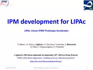
Commissioning experience from LIPAc in Japan
Commissioning experience from LIPAc in Japan. 8 th Open Collaboration Meeting on S uperconducting L inacs for Hi gh P ower P roton Beams (SLHiPP-8). Uppsala, June 13 th 2018 J. Marroncle – CEA Saclay. DSM/Irfu, CEA Saclay

Commissioning experience from LIPAc in Japan
E N D
Presentation Transcript
Commissioning experience from LIPAc in Japan 8th Open Collaboration Meeting on Superconducting Linacs for High Power Proton Beams (SLHiPP-8) Uppsala, June 13th 2018 J. Marroncle – CEA Saclay
DSM/Irfu, CEA Saclay B. Bolzon, N. Chauvin, S. Chel,F. Harrault, R. Gobin, J. Marroncle, F. Senée CIEMAT, Madrid D. Jimenez, J.M. Carmona, I. Podadera, J. A. Valera, M. Weber F4E (Fusion for Energy) – Garching P.Y. Beauvais, P. Cara, H. Dzitko, A. Jokinen, I. Moya, R. Heidinger IFMIF-EVEDA – Project team - Rokkasho J. Knaster, A. Marqueta, K. Nishiyama ,Y. Okumura, G. Pruneri, F. Scantamburlo INFN, Legnaro L. Bella, M. Communian, E. Fagotti, F. Grespan, A. Pisent National Institutes for Quantum and Radiological Science and technology, Rokkasho T. Akagi, R. Ichimiya, A. Ihara, A. Kasugai, T. Kitano, M. Komata, K. Kondo, K. Sakamoto, T. Shinya, M. Sugimoto Special thanks to these colleagues who helped me a lot while preparing this talk: B. Bolzon, P.Y. Beauvais, N. Chauvin, S. Chel, F. Senée
Outlook • IFMIF, LIPAc… in few words • Commissioning • Injector • High energy section of the LIPAc LIPAc Commissioning - SLHiPP8 - JM
IFMIF International agreement of the “Broader Approach” (Japan + Europe in Feb. 2007); BA = IFMIF/EVEDA + IFERC + JT60-SA IFMIF*: International Fusion Material Irradiation Facility for testing materials submitted to very high neutron fluxes for future Fusion Reactors. Very huge neutron source: flux ~ 1018 neutrons/m2/s Lithium Target 25 mm thick, 15 m/s beam profile = 20x5 cm2 Test Cell L M H 2 cw accelerators, 2 x 125 mA, 2 x 5MW • nuc. reactions • 7Li(d,2n)7Be • 6Li(d,n)7Be • 6Li(n,T)4He RFQ 5 MeV deuteron source 140 mA, 100 keV Superconducting Linac 40 MeV (Half Wave Resonators) LIPAc Commissioning - SLHiPP8 - JM
LIPAc: Linear IFMIF Prototype Accelerator Validation phase: prototype accelerator ➝ LIPAc 12.5 kW 625 kW 1125 kW 100 keV 5 MeV 9 MeV RF = 175 MHz Beam Dump ion source LIPAc = 125 mA cw, 9 MeV, 1.125 MW Beam Extraction LEBT RFQ MEBT ScHWR-Linac HEBT ECR source 2.45 GHz LIPAc Commissioning - SLHiPP8 - JM
contribution to LIPAc Most accelerator components designed and constructed in Europe Installed and commissioned in Rokkasho Injector + LEBT CEA Saclay RFQ INFN Legnaro QST SRF Linac CEA Saclay CIEMAT Madrid MEBT CIEMAT Madrid HEBT CIEMAT Madrid BD CIEMAT Madrid Diagnostics CEA Saclay CIEMAT Madrid 36 m Cryoplant CEA Saclay RF Power CIEMAT Madrid CEA Saclay SCK Mol Building Auxiliary System Control system Installation QST LIPAc Commissioning - SLHiPP8 - JM
General Plan for LIPAc commissioning D B A C • Phase A: injector Inst. & commissioning • 2014 - end 2017 • H+ & D+ (low dc) • Phase C: SRF + HEBT + LPBD / BD commissioning, but 0.1% cw • end 2018 – 1/2020 • SRF cryomodule assembling at Rokkasho • Installation SRF + HEBT + BD • H+ & D+(low dc) • Phase B: RFQ Inst. & commissioning MEBT + DP + LPBD (0.1% cw) • 2017 – fall 2018 • Assembling RFQ module, bead pull… • Moving RFQ to nominal location • Commissioning with MEBT+D-Plate just started, in progress • H+& D+(low dc) • Phase D: LIPAc • Up to 3/2020 • H+ & D+ beams, up to cw. LIPAc Commissioning - SLHiPP8 - JM
Injector commissioning Ion source + LEBT LIPAc Commissioning - SLHiPP8 - JM
Injector challenges Emax = 100 keV & ID+ ∼ 140 mA • High Space Charge: shorten the LEBT length for minimizing emittance growth • Limitation of the number of diagnostics: • 1 ACCT and no DCCT • Optimization of the LEBT configuration: • specific chamber used for several diagnostics AND vacuum equipment • High average power: around 15 kW at 100% d.c.: • Ensure an efficient water cooling of interceptive devices (Faraday cup, EMU shielding) • Need to implement cooling circuits on parts collecting only few % of the beam (electrodes) • Activation: shall be mastered to allow access for repair/improvement • Operation with proton beam at same Perveance (same SC effect) for accelerator debugging • EProton = 50 keV & IProton = 70 mA • Minimizing the duration of runs of D+ at high current and duty cycle • and of course, whatever the constraints the performances remain unchanged: • Normalized transverse emittance < 0.30 π·mrad·mm • Twiss parameters ensuring a good matching to the RFQ • crucial to prevent from excessive losses in the RFQ • Note: RFQ cone: φ=12 mm, angle ±8° LIPAc Commissioning - SLHiPP8 - JM
LEBT diagnostics • Particle loss: thermocouples on the last grounded electrode • SC compensation measurement: 1 FGA (4 Grid Analyzer) • Beam current: • 1 ACCT (at RFQ entrance -> transmission) • 1 "Faraday Cup”, Beam Stopper • ➝ Calorimetric measurements (FC, BS) • Emittance (Allison): 4 positions for 1 Emittancemeter EMU • Transverse beam profiles (fluorescence): 4 CID cameras, 1 CCD • Beam fraction species (Doppler): 1 deported spectrometer with a fiberscope • Note: a beam chopper is installed between the 2 solenoids 1st Diag. Chamber 2nd DC (removed for RFQ installation) (permanent) ECR source 2.45 GHz chopper EMU Fiberscope + remote spectrometer 4 CID (H/V) acc. column Dedicated diagnostic box for beam characterization during LEBT commissioning BS FGA BS CCD (V) or intensified CID (V) ACCT LIPAc Commissioning - SLHiPP8 - JM
Emittance: Allison scanner • 100% d.c. mode ➝ 15 kW (Max) • Emittance measurement made on LIPAc injector (CEA Saclay, 08/2012) • with a proton beam to avoid injector activation • Ep = 50 keV and 70 mA • ⇒ εx = 0.29 π·mm·mrad • RFQ acceptance εx,y = 0.30 π·mm·mrad (0.25 specification) Data taken during acceptance tests at CEA Saclay Saclay, August 2012 LIPAc injector (Proton) 2012 – D+ 100keV 10%cw • 0.29 π·mm·mrad Designed at CEA Saclay • 0.20 π·mm·mrad LIPAc Commissioning - SLHiPP8 - JM
y’3 y’2 y’1 y3 y1 y2 Allison scanner principle thanks to F. Senée intensity intensity intensity y’2 y’1 y’3 Angle y’ Angle y’ Angle y’ y’1 y1 Beam Axis y’2 y2 y’3 y3 LIPAc Commissioning - SLHiPP8 - JM
Doppler A fiberscope (20 m long Fujikura radiation hard) is plugged on the pipe chamber and to a remote spectrometer set in a shielding area to feed it with fluorescence Dα Balmer ray (interaction beam/RG). D+ beam: 150mA / 115mA (BS) – 100 keV – 3%cw LIPAc Commissioning - SLHiPP8 - JM
Commissioning steps Phase A3 • July 2017: 2 week D+(not published) 9/2017: adjustment of accelerator column Phase B0 (RFQ already installed) • 12/17-2018: 2 weeks D+ (several H+) 12/18 to 01/2019 new D+ campaign to work in cw is foreseen (6 to 8 weeks) 11/2012: acceptance test at Saclay Phase A1 (~20 w) • Nov.-Dec. 2014: 5 week H+ • April-June 2015: 5 week H+ • July-Sept. 2015: 0.5/9 week H+ /D+ Phase A2 (~21 w) • Sept.-Dec. 2015: 4/3.5 weeks H+/D+ • Jan.-June 2016: 8.5 weeks H+ • Oct.-Nov. 2016: 5 weeks D+ Phase A2: B. Bolzon, et al., IPAC 2016, WEPMY033 B. Bolzon, et al., ECRIS 2016, WECO01 (also phase A1) B. Bolzon, et al., Fusion Eng. Des. (2018) (also A1/A3) https://doi.org/10.1016/j.fusengdes.2018.04.128 L. Bellan et al., Source and LEBT beam preparation for IFMIF-EVEDA RFQ, LINAC 2016, TUPRC005, East Lansing, MI, USA Phase A1: Y. Okumura, et al., Rev. Sci. Instrum. 87 (02) (2016) A739 K. Shinto, et al., Rev. Sci. Instrum. 87 (02) (2016) A727 R. Gobin, et al., Rev. Sci. Instrum. 87 (02) (2016) A726 B. Bolzon, et al., IBIC 2015, TUPB008 N. Chauvin et al., “beam commissioning of the linear IFMIF Prototype Accelerator Injector: measurements and simulations’, IPAC13, Shanghai, China. A2 A3 A1 LIPAc Commissioning - SLHiPP8 - JM
Few results for A1 D+ beam: 91mA – 100 keV –cw D+ beam: 105 mA – 100 keV – 9.5% D3+ D+ D2+ Φplasma=10mm D+ beam: 155/125 mA – 100 keV – 10% No emittance improvement evidence after Kr injection After background subtraction EMU 81% D+ / similar to Doppler This agreement does not work for proton beam at 50 keV! TBI LIPAc Commissioning - SLHiPP8 - JM
Few results for A2 L. Bellan (INFN Legnaro) EMU located downstream the cone entrance divergence D+: 100 keV, 3% compromise: end 2016 Sol. 2 (A) Sol. 1 (A) strong focusing area During the long commissioning process allowing to counteract many problems, few matching difficulties between experimental and calculated variables appeared… discrepancy between injector electrodes and the design were measured and fixed on 09/2017 design before correction LIPAc Commissioning - SLHiPP8 - JM
Once electrodes fixed (12/2017) N. Chauvin, meeting at Rokkasho, Dec. 2017 D+ 165 mA, 100 keV, 3% D+, 100 keV, 5% (2ms/40ms) Sol1 275A big improvement of Emittance, clearly under 0.25 π·mrad·mm Summary Report to the BA SC #22 (26/04/2018) “The beam emittance values now reliably meet and even exceed the specifications in pulsed operation. They are also coherent with the beam simulations performed by CEA and INFN” LIPAc Commissioning - SLHiPP8 - JM
Few lessons learned • Importance to develop relevant beam dynamics simulations, starting from particle extraction with respect to the real design • Accurate accelerator alignment: it is even more relevant for the LEBT made of 2 solenoids which slightlyrotate the beam. Misalignment implies to correct with steerers and tuning becomes then difficult to interpret and implement! • Plasma chamber must have a high cleanliness level to generate numerous e-, H+ or D+… To be banned: oil pumps! Indeed hydrocarbons must pollute the plasma chamber generating electric sparks… compromising high electric field behavior as well as its stability • Space Charge: no significant effect has been observed by injecting Kr in our conditions. Note that Kr may neutralize beam particles, decreasing the beam intensity! • Keep tracks of all modifications or actions done on the system. • H/2 and D are similar in term of SC, but not similar at the exit of the plasma chamber (extraction system can not be the same!) commissioning • Not easy to extrapolate pulsed to cw results with stable beam characteristics LIPAc Commissioning - SLHiPP8 - JM
Next commissioning phases LIPAc Commissioning - SLHiPP8 - JM
LIPAc diagnostics Glossary: ACCT: AC Current Transformer BLoM: Beam Loss Monitor RGBLM: Residual Gas Bunch Length Monitor BPM: Beam Position Monitor DCCT: DC Current Transformer FC: Faraday Cup FFC: Fast Faraday Cup FCT: Fast Current Transformer IPM: Ionization Profile Monitor FPM: Fluorescence Profile Monitor µLoM: Micro Loss Monitor BLoM: Beam Loss Monitor BPM: Beam Position Monitor CT: Current Transformer FFC: FastFaraday Cup FPM: Fluorescence Profiler Monitor IPM: Ionization Profiler Monitor µLoM: micro Loss Monitor RGBLM: Residual Gas Bunch Length Monitor IPM SEM Grids (1m from slits) ACCT + DCCT • 2 Slits (Emittance) D-Plate • 2 BPMs (striplines) FPM • 1 BPM (Stripline) • FFC • RGBLM Emittance meter ∼ 20 BLoMs for the whole end-accelerator FC Species fraction measurement ACCT IPM ACCT + FCT SEM Grids ACCT 3 x 8 µLoM 4 Profilers (CCD camera) 4 grids analyser 9 MeV 5MeV • 2 BPM • 3 BPM 100 keV 8 BPM (cryo) • 4 BPM (striplines) 1 Slit (E.spread) FPM LIPAc Commissioning - SLHiPP8 - JM
Diagnostic Plate • Transverse emittance • 2 horizontal and vertical slits (100 or 200µm) • Steerers HV + SEM grids • Beam energy and beam position • 3 BPM (Strip-lines) • Bunch length • Beam / residual gas ionization • electron extraction under E field • Magnetic chicane (mono-energetic) • MCP detection (ToF wrt RF signal) • Transverse profile monitors • 1 IPM + 2 FPM for X&Y profiles • Beam current • ACCT+DCCT (DP) • Beam Loss Monitors • more than 4 ICs LIPAc Commissioning - SLHiPP8 - JM
LIPAc commissioning sketches top view sketches LPBD < 0.1% cw Phase B (0.1% cw) Phase C (0.1% cw…) Phase D (up to 100% cw) LIPAc Commissioning - SLHiPP8 - JM
RFQ & LEBT commissioning – Phase B • duty cycle < 0.1% cw • Rough expectations • B1 beam line characterization for H+ up to 8/2018 • beam passing through RFQ, MEBT, diagnostic tests… • Before end 2018: • Tests with maximum length pulses • D+ beams short length (10µs) and back to H+ • Activation tests LIPAc Commissioning - SLHiPP8 - JM
SRF Linac commissioning – Phase C • duty cycle < 0.1% cw • Rough expectations • HEBT & BD installation up to 1/2019 • Ready to take beam (low power) • SRF Linac will be installed in the vault by spring 2019 LIPAc Commissioning - SLHiPP8 - JM
LIPAc commissioning – Phase D • duty cycle: 0.1% up to cw • Rough expectations • SRF Linac • 2/2018: first components received at Rokkasho • fall 2018: assembling start • spring 2019: installation in the vault and conditioning • 1/2020: ready for beam operation • Beam up to 31/03/2020 LIPAc Commissioning - SLHiPP8 - JM
NPM summary • Commissioning of LIPAc is a long way • Injector commissioning • Almost finished with correct TWISS parameters and quite low emittance compliant to RFQ • Another period is foreseen increase the duty cycle in D+… up to cw • Higher energy part • RFQ commissioning in starting phase • High power BD (able to handle 1.1 MW) installation will start soon • SRF Linac • assembly in Rokkasho will start by fall 2018 • Ready for commissioning on beginning 2020 • End March 2020 LIPAc Commissioning - SLHiPP8 - JM
spares LIPAc Commissioning - SLHiPP8 - JM
Pulse length monitor LIPAc Commissioning - SLHiPP8 - JM
Transversal emittance at high energy X1 ∆1 ∆2 X2 ∆3 X3 0,75 1,50 2,25 X4 0 X5 X6 SEM grids (plan de fils) X7 fentes X8 ∆X beam axis Déviateur beam beamlet X LIPAc Commissioning - SLHiPP8 - JM
Radiation background LIPAc radiation background study New shielding • New shielding (polyethylene disks, plates…) • ➟ neutrons • Fluence, calculated over 6 months cw 75 55 145 125 105 45 35 25 95 115 15 5 135 65 85 A. Marchix – January 2012 (only BD) • Old shielding (concrete wall…) • ➟ neutrons, γ • Fluence, calculated over 6 months cw Old shielding 2 3 1 UNED study (~2008) Rokkasho meeting, March 2012 - PY Beauvais