Download
1 / 134
1.41k likes | 1.78k Views
Chapter 6 :: Topics. Introduction Assembly Language Machine Language Programming Addressing Modes Lights, Camera, Action: Compiling, Assembling, & Loading Odds and Ends. Jumping up a few levels of abstraction Architecture: programmer’s view of computer

E N D
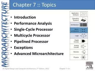
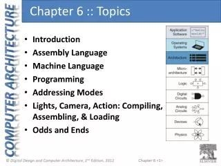
Chapter 6 :: Topics • Introduction • Assembly Language • Machine Language • Programming • Addressing Modes • Lights, Camera, Action: Compiling, Assembling, & Loading • Odds and Ends
Jumping up a few levels of abstraction Architecture:programmer’s view of computer Defined by instructions & operand locations Microarchitecture: how to implement an architecture in hardware (covered in Chapter 7) Introduction
Instructions:commands in a computer’s language Assembly language:human-readable format of instructions Machine language:computer-readable format (1’s and 0’s) MIPS architecture: Developed by John Hennessy and his colleagues at Stanford and in the 1980’s. Used in many commercial systems, including Silicon Graphics, Nintendo, and Cisco Once you’ve learned one architecture, it’s easy to learn others Assembly Language
President of Stanford University Professor of Electrical Engineering and Computer Science at Stanford since 1977 Coinvented the Reduced Instruction Set Computer (RISC) with David Patterson Developed the MIPS architecture at Stanford in 1984 and cofounded MIPS Computer Systems As of 2004, over 300 million MIPS microprocessors have been sold John Hennessy
Underlying design principles, as articulated by Hennessy and Patterson: Simplicity favors regularity Make the common case fast Smaller is faster Good design demands good compromises Architecture Design Principles
Instructions: Addition • add: mnemonic indicates operation to perform • b, c: source operands (on which the operation is performed) • a:destination operand (to which the result is written) C Code a = b + c; MIPS assembly code add a, b, c
Instructions: Subtraction • Similar to addition - only mnemonic changes • sub:mnemonic • b, c: source operands • a:destination operand C Code a = b - c; MIPS assembly code sub a, b, c
Design Principle 1 Simplicity favors regularity • Consistent instruction format • Same number of operands (two sources and one destination) • easier to encode and handle in hardware
Multiple Instructions • More complex code is handled by multiple MIPS instructions. C Code a = b + c - d; MIPS assembly code add t, b, c # t = b + c sub a, t, d # a = t - d
Design Principle 2 Make the common case fast • MIPS includes only simple, commonly used instructions • Hardware to decode and execute instructions can be simple, small, and fast • More complex instructions (that are less common) performed using multiple simple instructions • MIPS is a reduced instruction set computer (RISC), with a small number of simple instructions • Other architectures, such as Intel’s x86, are complex instruction set computers (CISC)
Operands • Operand location: physical location in computer • Registers • Memory • Constants (also called immediates)
Operands: Registers • MIPS has 32 32-bit registers • Registers are faster than memory • MIPS called “32-bit architecture” because it operates on 32-bit data
Design Principle 3 Smaller is Faster • MIPS includes only a small number of registers
Operands: Registers • Registers: • $before name • Example: $0, “register zero”, “dollar zero” • Registers used for specific purposes: • $0 always holds the constant value 0. • the saved registers, $s0-$s7, used to hold variables • the temporary registers, $t0 - $t9,used to hold intermediate values during a larger computation • Discuss others later
Instructions with Registers • Revisit add instruction C Code a = b + c MIPS assembly code # $s0 = a, $s1 = b, $s2 = c add $s0, $s1, $s2
Operands: Memory • Too much data to fit in only 32 registers • Store more data in memory • Memory is large, but slow • Commonly used variables kept in registers
Word-Addressable Memory • Each 32-bit data word has a unique address
Reading Word-Addressable Memory • Memory read called load • Mnemonic:load word (lw) • Format: • lw $s0, 5($t1) • Address calculation: • add base address($t1) to the offset (5) • address = ($t1 + 5) • Result: • $s0 holds the value at address ($t1 + 5) • Any register may be used as base address
Reading Word-Addressable Memory • Example: read a word of data at memory address 1 into $s3 • address = ($0 + 1) = 1 • $s3 = 0xF2F1AC07 after load Assembly code lw $s3, 1($0) # read memory word 1 into $s3
Writing Word-Addressable Memory • Memory write are called store • Mnemonic:store word (sw)
Writing Word-Addressable Memory • Example: Write (store) the value in $t4 into memory address 7 • add the base address ($0) to the offset (0x7) • address: ($0 + 0x7) = 7 • Offset can be written in decimal (default) or hexadecimal Assembly code sw $t4, 0x7($0) # write the value in $t4 # to memory word 7
Byte-Addressable Memory • Each data byte has unique address • Load/store words or single bytes: load byte (lb) and store byte (sb) • 32-bit word = 4 bytes, so word address increments by 4
Reading Byte-Addressable Memory • The address of a memory word must now be multiplied by 4. For example, • the address of memory word 2 is 2 × 4 = 8 • the address of memory word 10 is 10 × 4 = 40 (0x28) • MIPS is byte-addressed, not word-addressed
Reading Byte-Addressable Memory • Example: Load a word of data at memory address 4 into $s3. • $s3 holds the value 0xF2F1AC07 after load MIPS assembly code lw $s3, 4($0) # read word at address 4 into $s3
Writing Byte-Addressable Memory • Example: stores the value held in $t7 into memory address 0x2C (44) MIPS assembly code sw $t7, 44($0) # write $t7 into address 44
Big-Endian & Little-Endian Memory • How to number bytes within a word? • Little-endian: byte numbers start at the little (least significant) end • Big-endian: byte numbers start at the big (most significant) end • Word address is the same for big- or little-endian
Big-Endian & Little-Endian Memory • Jonathan Swift’s Gulliver’s Travels: the Little-Endians broke their eggs on the little end of the egg and the Big-Endians broke their eggs on the big end • It doesn’t really matter which addressing type used – except when the two systems need to share data!
Big-Endian & Little-Endian Example • Suppose $t0 initially contains 0x23456789 • After following code runs on big-endian system, what value is $s0? • In a little-endian system? • sw $t0, 0($0) • lb $s0, 1($0)
Big-Endian & Little-Endian Example • Suppose $t0 initially contains 0x23456789 • After following code runs on big-endian system, what value is $s0? • In a little-endian system? • sw $t0, 0($0) • lb $s0, 1($0) • Big-endian: 0x00000045 • Little-endian: 0x00000067
Design Principle 4 Good design demands good compromises • Multiple instruction formats allow flexibility • add, sub: use 3 register operands • lw, sw: use 2 register operands and a constant • Number of instruction formats kept small • to adhere to design principles 1 and 3 (simplicity favors regularity and smaller is faster).
Operands: Constants/Immediates • lw and swuse constants or immediates • immediately available from instruction • 16-bit two’s complement number • addi: add immediate • Subtract immediate (subi) necessary? C Code a = a + 4; b = a – 12; MIPS assembly code # $s0 = a, $s1 = b addi $s0, $s0, 4 addi $s1, $s0, -12
Machine Language • Binary representation of instructions • Computers only understand 1’s and 0’s • 32-bit instructions • Simplicity favors regularity: 32-bit data & instructions • 3 instruction formats: • R-Type: register operands • I-Type: immediate operand • J-Type: for jumping (discuss later)
R-Type • Register-type • 3 register operands: • rs, rt: source registers • rd: destination register • Other fields: • op: the operation code or opcode(0 for R-type instructions) • funct: the function • with opcode, tells computer what operation to perform • shamt: the shift amount for shift instructions, otherwise it’s 0
R-Type Examples Note the order of registers in the assembly code: add rd, rs, rt
I-Type • Immediate-type • 3 operands: • rs, rt: register operands • imm: 16-bit two’s complement immediate • Other fields: • op: the opcode • Simplicity favors regularity: all instructions have opcode • Operation is completely determined by opcode
I-Type Examples Notethe differing order of registers in assembly and machine codes: addirt, rs, imm lwrt, imm(rs) swrt, imm(rs)
Machine Language: J-Type • Jump-type • 26-bit address operand (addr) • Used for jump instructions (j)
Power of the Stored Program • 32-bit instructions & data stored in memory • Sequence of instructions: only difference between two applications • To run a new program: • No rewiring required • Simply store new program in memory • Program Execution: • Processor fetches(reads) instructions from memory in sequence • Processor performs the specified operation
The Stored Program Program Counter (PC): keeps track of current instruction
Interpreting Machine Code • Start with opcode: tells how to parse rest • If opcodeall 0’s • R-type instruction • Function bits tell operation • Otherwise • opcode tells operation
Programming • High-level languages: • e.g., C, Java, Python • Written at higher level of abstraction • Common high-level software constructs: • if/else statements • for loops • while loops • arrays • function calls
Ada Lovelace, 1815-1852 • Wrote the first computer program • Her program calculated the Bernoulli numbers on Charles Babbage’s Analytical Engine • She was the only legitimate child of the poet Lord Byron
Logical Instructions • and, or, xor, nor • and: useful for maskingbits • Masking all but the least significant byte of a value: • 0xF234012F AND 0x000000FF = 0x0000002F • or: useful for combiningbit fields • Combine 0xF2340000 with 0x000012BC: • 0xF2340000 OR 0x000012BC = 0xF23412BC • nor: useful for inverting bits: • A NOR $0 = NOT A • andi, ori, xori • 16-bit immediate is zero-extended (not sign-extended) • nori not needed
Shift Instructions • sll: shift left logical • Example:sll $t0, $t1, 5 # $t0 <= $t1 << 5 • srl: shift right logical • Example:srl $t0, $t1, 5 # $t0 <= $t1 >> 5 • sra: shift right arithmetic • Example:sra $t0, $t1, 5 # $t0 <= $t1 >>> 5