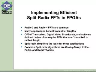
Implementing Complex Algorithms in FPGAs: A Comprehensive Workshop by Dr. Steve Chappell
930 likes | 1.06k Views
Join Dr. Steve Chappell, Director of Apps Engineering, in this in-depth workshop focused on implementing complex algorithms in FPGAs. This workshop covers essential materials such as course workbooks, tutorials, application notes, and integrated help systems. Explore the opportunities of using hardware coprocessors and understand the design flows utilizing DK and Handel-C languages. Learn about FPGA architecture, algorithm acceleration, and practical lab sessions that will enhance your skills in hardware-software co-design. Perfect for engineers seeking to leverage FPGA technology.

Implementing Complex Algorithms in FPGAs: A Comprehensive Workshop by Dr. Steve Chappell
E N D
Presentation Transcript
Implementing Complex Algorithms in FPGAs Workshop Dr Steve Chappell Director Apps Engineering
Workshop Materials • For the Labs • Course Workbook, Tutorials and Application Notes • DK integrated help system • On your Workstations • DK, PDK • Target Platforms • RC100, RC1000
Contents • Introductions • About Celoxica • The Basics • Opportunities with a HW Coprocessor • Target Boards • Design Flows – DK and Handel-C in brief • Handel-C Language • Tool Connectivity • Platform Developers Kit • Platform Abstraction • Codesign • Appendices • Technology, Applications, CUP Lab#1 Lab#2 Labs#3,4
About Celoxica • System EDA company • Design Tools, FPGA Boards, Consultancy and Services • Incorporated on the 25th September 2000 (Formerly ESL) • Market leader in complete solutions for software-compiled system design • Core Technology is DK incorporating the Handel-C programming language • A senior management wealth of EDA and electronics industry experience • Industry leading partners: • Strong Links with Research & Development • Technology and expertise based upon decades of research into state-of-the-art at The University of Oxford • Chief Science Officer Ian Page, visiting Professor at the Imperial College of Science, Technology & Medicine, London • Established and active University Program (700 institutions world-wide) • Investors • Premier league investors including Intel
Supporting Argonne • Augmented Cluster supplied by Linux Networks • Incorporating Tarari CPP cards and Software drivers • Celoxica Development Kit for FPGA content • Ensuring successful deployment and evaluation • Cluster support by Linux Networks • Augmented Application and CPP card support by Celoxica
The Basics Opportunities and Challenges Essence of an FPGA Design Flows
Opportunities with a HW Co-processor • Algorithm Acceleration • Exploit the parallelism in algorithms to increase performance with implementation in custom (parallel) hardware • Algorithm Offload • Exploit the coprocessor to free CPU resource • e.g., in an SSL proxy, the CPU can always handle more TCP traffic if algorithms such as RSA and 3DES are moved to a coprocessor • For PCI-based coprocessor cards candidate algorithms include ones where CPU execution time far exceeds data transfer time over PCI • Full analysis needs to consider: • Time required to perform the algorithm in the Co-processor • System application performance improvement – Amdahl’s Law
Opportunities with FPGAs • FPGA architecture • What it means for applications • “Soft” Hardware • Reconfigurability/Programmability • Integer processors (FP is “resource expensive”) • Wide data paths • Parallel Computation • Challenges to deployment in enterprise computing • Development complexity • IP deployment and integration • Design Framework and methods • Data Bandwidth to/from coprocessor • Choosing the right applications
> Block RAM > Soft Cores Processor > CLB > Multipliers > Processor > Application Essence of an FPGA > SRAM Field Programmable Gate Array CLB’s+IOB’s+Interconnect Matrix
Target Boards RC100, RC1000, RC2000 Tarari CPP
RC-100 • Xilinx Spartan2-200 FPGA • 2MB ZBT SRAM, in 2 36-bit banks. 8MB Flash RAM • 50 pin expansion header, PS/2 mouse/keyboard, parallel port • Video input decoder, VGA output DAC • Two 7-segment LED displays • 80MHz maximum clock
RC-1000 • PCI card, DMA transfers > 110 MB/sec sustained • Xilinx Virtex-2000 FPGA • 8MB SRAM, in 4 32-bit banks • 2 PMC slots • 50 auxiliary I/O pins • Programmable clock
RC-1000 13
RC-2000 • Virtex II 2V3000-4, 2V6000-4 and 2V6000-6 FPGAs • 64bit 66MHz PCI bus • 6 banks of ZBT SRAM offering a total of either 12Mb or 24Mb • Front-panel I/O up to 146 lines, dependant on options • 64 I/O lines via PMC connector • 16Mb Flash for configuration storage • 2 Programmable clocks • Options include: • 16Mb additional ZBT SRAM in 2 banks • 128Mb DDR Ram
RC-2000 15
CPP – Basic Board Architecture • Two CPE’s – Content Processing Engines • Virtex-II 1000 FPGA: • Eight LEDs • 2x 1MB SRAM • Connection to CPC • CPC – Content Processing Controller • 256MB DDR SDRAM • PCI Bus to Host
Design Flows DK and Handel-C
Designing acceleration IP • Traditional Options – HDL based design • Purchase FPGA (HW) development tools • Hire/use HW engineers • Pay 3rd Party development fees • The Alternative – “Software Compiled System Design” • Use Celoxica Content Processing Development Kit • Development framework with Example Acceleration IP • Comprehensive Hardware-Software Co-simulation environment • Tool and Language Connectivity • Enable SW engineers and/or increase HW engineer productivity
Why a Software Language Based Approach for System Design? • Some problems are better expressed as a software algorithm • Software Reference designs can be utilized • Designs are often specified by a C/C++ executable • Simplifies and delays hardware-software partitioning • Software development techniques can be used • Brings hardware and software teams closer together • New Possibilities …
RC100 • RC100 prototyping board • $10 FPGA • Commodity memory chips • Video Input and Output 1
RC100 • RC100 prototyping board • $10 FPGA • Commodity memory chips • Video Input and Output 2
CPDK for developing acceleration IP • The Content Processing Development Kit includes • Celoxica “DK” and supporting libraries • Consisting of • “Software Compiled System Design” environment • Simple design flow with integrated Simulation and direct implementation • Similar SW/HW design methods simplifies design exploration and optimal allocation of functionality between SW and HW • Verification and Debug using a Symbolic Debugger • Connectivity and co-simulation with SW and HDL cores • API’s to hide complexity • Enabling your software and hardware developers • To rapidly develop acceleration IP
Handel-C direct to FPGA, Minimum Tool Chain Easy-to-learn language – ISO-C (ANSI-C) Design of hardware and software in parallel with co-simulation Design Flow FPGA Vendor’s Tools Place & Route Celoxica DK1 – Rapid Design Handel-C Simulate Compile Final Hardware Netlist Configure
HW SW External IP (optional) Minimal Tool Chain StandardisedAPI’s Similar Languages PlatformAbstraction Development Flow Specification Algorithm Definition LIBS SW Tool DK C Handel-C HW SW Partition BSP BSP OS Develop HLL Co-Verification Implementation HDL C EDIF LIB EDIF OBJ Compile Host CPU CPP
HW SW API’s Enable Rapid Co-verification Specification DK Nexus C Handel-C HW SW BSP BSP HDL-Simulator SW and/or ISS Virtual Platform Implementation • “Virtual Platform” for Co-simulation and Co-design • Cycle-accurate HLL simulator for Acceleration IP modelling • Extendable Co-Sim to: C/C++, HDL, System-C, ISS
DK User Interface Simulate Build Syntax highlighting Break-points Multithreaded Debug File view Symbol view Watch variables Clock Cycles Info
Handel-C in Brief • Handel-C is based on ANSI C • Well-defined semantics similar to OCCAM/CSP • Additions: • support for parallelism • channels for communications between parallel processes • operators for detailed control of hardware • constructs for RAM, ROM, interfacing, etc.
Core Language Features • Standard C (if, while, switch etc) including • Functions • Structures • Pointers • par {…} construct for parallelism • Simple model of timing • each assignment is one clock cycle • Arbitrary widths on variables • Enhanced bit manipulation operators • Sharing/Copying expressions • Support for hardware constructs • Multiple clock domains, RAM, ROM, external interfaces
Handel-C describes Hardware! • No side effects in expressions • i.e. statements like a = b*c++; are not supported • No floating point • Floating point not directly supported by Handel-C. • Library support provided for fixed and floating point arithmetic • No run-time recursion • Due to the absence of any kind of ‘call stack’ in hardware. • Limited standard library (i.e. no printf, fopen etc.) • However, DK1.1 allows direct calls to external functions written in C/C++, and these could incorporate file I/O, user interaction, recursion, etc.
voidmain(void) { unsigned6a; a=45; } a = 1 0 1 1 0 1 = 0x2d MSB LSB Variables • Handel-C has onebasic type - integer • May be signed orunsigned • Can be any width, not limited to 8, 16, 32 etc. Variables are mapped to hardwareregisters.
Bit Manipulation Operators • Extra operators have been added to allow more ‘hardware like’ bit manipulation: • << Shift Left b = a<<2; • >> Shift Right b = a>>1; • <- Take least significant bits b = a<-5; • \\ Drop least significant bits b = a\\5; • @ Concatenate bits b = a@c; • [ ] Bit Selection b = a[4:1];
[MSB :LSB ]- bit selection (range of bits) a = 1 0 1 1 0 1 = 0x2d b = a[4:1] b = 0 1 1 0 = 0x6 Example Bit Manipulation
Bit Manipulation 2 • Other bit manipulation examples: signed int 4a; signedb,c,d; a = 0b1100; b = a<<1; // b = 0b1000 b = a>>1; // b = 0b1110 c = a[2:1]; // c = 0b10 c = a<-2; // c = 0b00 c = a\\2; // c = 0b11 d = a @ a; // d = 0b11001100
Timing model • Assignments and delay statements take 1 clock cycle • Combinatorial Expressions computed between clock edges • Most complex expression determines clock period • Example: takes 1+n cycles (n is number of iterations) index = 0; // 1 Cycle while (index < length){ if(table[index] = key) found=index; // 1 Cycle else index = index+1; // 1 Cycle } }
SequentialBlock ParallelBlock // 3 Clock Cycles { a=1; b=2; c=3; } // 1 Clock Cycle par{ a=1; b=2; c=3; } Parallelism • Handel-C blocks are by default sequential • par{…}executes statements in parallel • par block completes when all statements complete • Time for block is time for longest statement • Can nest sequential blocks in par blocks
Sequentialcode Parallelcode for(i=0;i<10;i++) { array[i]=0; } par(i=0;i<10;i++) { array[i]=0; } More Parallelism • Example – array initialisation • Sequential version takes 20 clock cycles • for() loop has 1 cycle overhead for increment • Parallel version takes 1 clock cycle • Replicated par() builds hardware to execute all 20 iterations in a single cycle • Allows trade-off between hardware size and performance
c a b Chan unsigned 6 c; { … c!a+1; //write a+1 to c … } { … c?b; //read c to b … } Channels • Allow communication and synchronisation between two parallel branches • Semantics based on CSP: unbuffered (synchronous) send and receive • Declaration • Specifies data type to be communicated
Sharing Hardware for Expressions • Functions provide a means of sharing hardware for expressions • By default, compiler generates separate hardware for each expression • Hardware is idle when control flow is elsewhere in the program • Hardware function body is shared among call sites {… x= x*a + b; y= y*c +d } int mult_add(int z,c1,c2){ return z*c1 + c2; } { … x= mult_add(x,a,b); y= mult_add(y,c,d); }
Replicating Hardware for Expressions • Inline Functions are expanded at the call site • Provide for functional abstraction of complex hardware inline complex mult_complex(complex x,y){ complex z; par{ z.re = x.re*y.re – x.im*y.im; z.im = x.re*y.im + x.im*y.re; } return z; } complex x1,y1,x2,y2,z1,z2; … par{ z1 = mult_complex(x1,y1); z2 = mult_complex(x2,y2); }
Macro procedures • macro proc is similar to an inline function, but is expanded at compile time. • They also allow for arbitrary bit width calculations • The following generates a reusable timer: macro proc usleep(ms) { #define TENTH_SEC CLOCK_RATE/10 unsigned (log2ceil(TENTH_SEC)) Counter; Counter = TENTH_SEC * (0@ms) ; while (Counter) Counter--; }
// Breaking up complex expressions int 15 a, b; signal <int> sig1; static signal <int> sig2=0; //default value of 0 a = 7; par { sig1 = (a+34)*17; sig2 = (a<<2)+2; b = sig1 + sig2; } Signals • A signal behaves like a wire - takes the value assigned to it but only for that clock cycle. • The value can be read back during the same clock cycle. • The signal can also be given a default value.
Interfaces - Introduction • Interfaces allow Handel-C designs to connect to external hardware and logic. • Three types of interfaces • Buses – used for connecting to external pins • Ports – used for creating connection points for external logic. • e.g. Creating the ports for a VHDL entity • User Defined – used for including external logic blocks inside a Handel-C design. • e.g. Including an EDIF black box inside a deign.
P1 x x P2 Address P3 P4 Interfaces – Buses • Makes connections to pins on the FPGA. • Bus types • Output • Input – direct, clocked and latched input • Tri-state – direct, clocked and latched tri-state interface bus_in(int 4) Address() with {data={P1,P2,P3,P4}}; x=Address.in;
Input1 Output Handel-C black box Input2 Interfaces – Ports • Allows connection points for external logic to be specified. e.g. Defining the ports for a ‘black box’ VHDL entity • Port types: Input, Output //Declare Ports interface port_in(int 4Input1) InputPort1(); interfaceport_in(int 4Input2) InputPort2(); interfaceport_out() OutputPort(int 4 Output = OutReg);
Handel-C Design EDIF Module pipe_mult.edf A Result B Interfaces – User Defined • Allows external logic blocks to be used inside a Handel-C design. e.g. Using an EDIF core. //Instantiate connections to core interface pipe_mult(int 4 Result) Multiplier(int 4A, int 4B);
chan unsigned 8 ComChan; set clock = external "C1"; void main(void) { unsigned 8 x; do { x++; ComChan ! x; }while(1); } extern chan unsigned 8 ComChan; set clock = external "C2"; void main(void) { unsigned 8 y; do { ComChan ? y; }while(1); } Multiple Clock Domains - example Domain1.c Domain2.c
Handel-C Summary • Handel-C is based on ANSI C • Well-defined semantics similar to OCCAM/CSP • Additions: • support for parallelism • channels for communications between parallel processes • operators for detailed control of hardware • constructs for RAM, ROM, interfacing, etc.