Download
1 / 13
140 likes | 280 Views
The Quasi-Kinematic Contact (QKC) method offers significant advantages in engine assembly precision, featuring superior repeatability and cost-effectiveness compared to traditional kinematic designs. Utilizing innovative ball and groove compliance techniques, the QKC design effectively addresses surface irregularities and enhances elastic recovery, ensuring optimal alignment and reduced assembly errors. This technology is critical for high-volume production, with specifications tailored to achieve outstanding performance in automotive applications like the Ford V6 engines. Explore the characteristics, geometry, and mechanics behind QKC designs to optimize manufacturing processes.

E N D
QKC characteristics: Arc contact Submicron repeatability Stiff, sealing contact Less expensive than KCs Easier to make than KCs QKC Function: Ball & groove comply Burnish surface irregularities Elastic recovery restores gap F or D dfinal d= 0 dinitial Quasi-Kinematic (QKC) alignment Spherical Protrusion Groove Seat Side Reliefs Feature Height, mils Distance along Cone Face, [inches]
+ BOLT BLOCK + = + CAST FORM TOOL FINISHED BEDPLATE PEG Details of QKC element geometry PAIRS OF QKC ELEMENTS OR TYPE 2 GROOVE MFG. ASSEMBLED JOINT
+ + Which variation of QKC to use • Design A Design B • In Design A, Peg deforms on edge -> reduced repeatability OR
y x QKC methods vs kinematic method Components and Definitions Relief Relief Cone Seat Ball Groove Surface Peg Surface Contact Point Force Diagrams
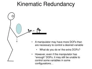
Material Contact Stiffness fn(dn) QKC Model Force/Torque Geometry Displacements Stiffness Modeling QKC stiffness Geometry Material Applied Loads [Fp & Mp] Resultant Forces [ni & Fi] Deflections d -> Dr Relative Error
^ l ^ n ^ s Rotating CS ^ k ^ ^ l n Rc ^ i QKC contact mechanics • MECHANICS: • • Use Rotating Coordinate System • • Assume Sinusoidal Normal Distance of Approach • • Obtain Contact Stress Profile as Function of Above • • Integrate Stress Profile in Rotating CS thru contact
10 mm Coupling + Others 5 mm Process 0 mm Example: DuratecTM assembly • Characteristics: • Ford 2.5 & 3.0 L V6 • > 300,000 Units / Year • Cycle Time: < 30 s Rough Error Budget
C C L L de JL JR r Block Bore Bedplate Bore a Assembly Bolts Bedplate C B Halves Block Block Bedplate Example: Assembly of DuratecTM block & bedplate COMPONENTS ERROR ASSEMBLY de MAX = 5 microns
Bearing assemblies in engines Block Block Main Bearing Half Crank Shaft Journal Piston Bedplate Main Bearing Half Crank Shaft Bedplate Main Bearing Halves
Results of DuratecTM QKC Research MANUFACTURING: DESIGN:
JL Cap Probe 1st Block Fixture CMM Head Bedplate Fixture Bedplate JR Cap Probe Axial Axial Cap Probe Sensitive 2nd Block Fixture Engine assembly performance (Range/2) = 1.35 mm (Range/2)|AVG = 0.65mm 9