Project Information
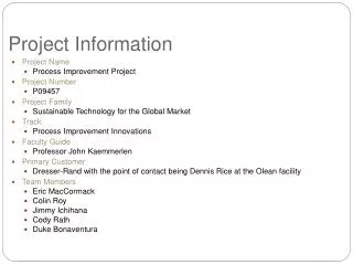
Project Information. Project Name Process Improvement Project Project Number P09457 Project Family Sustainable Technology for the Global Market Track Process Improvement Innovations Faculty Guide Professor John Kaemmerlen Primary Customer Dresser-Rand Piping and Packaging Area

Project Information
E N D
Presentation Transcript
Project Information • Project Name • Process Improvement Project • Project Number • P09457 • Project Family • Sustainable Technology for the Global Market • Track • Process Improvement Innovations • Faculty Guide • Professor John Kaemmerlen • Primary Customer • Dresser-Rand Piping and Packaging Area • Team Members • Eric MacCormack • Colin Roy • Jimmy Ichihana • Cody Rath • Duke Bonaventura
Project Approach For 25 years process improvement has been overlooked at Dresser-Rand’s facility. There are many opportunities at making improvements throughout the facility. • Many problems could be individual capstone projects • Proposing quick and inexpensive solutions to several problem areas is the focus of this project
Project Approach After initial review of Dresser-Rand Piping and Packaging area it has been determined that the best approach is to break up the floor into several subsystems: • Facility Layout • Weld Booths • Consignment and VMI Inventory • Tubing and Instrumentation • Pipe Prep – Cutting and Bending • Hydro and Cleaning • Final Packaging
Overviewof Plant 1 Not in Packet
Crane Safety “Approximately 50 or more people die, and hundreds more are injured every year in the United States as a result of overhead crane accidents. Overhead crane accidents are considered one of the leading causes of death or serious injury in the construction/manufacturing industry.” “OSHA requires that employers take every precaution possible to prevent overhead crane injuries. When an employer’s negligence causes or contributes to injury or death in overhead crane accidents, they can be held liable for any damages that were caused. Parties who have been injured in overhead crane accidents caused or contributed to be another party’s negligence have the legal right to seek compensation for there losses.” Source: Overhead Crane Accidents http://www.onlinelawyersource.com/personal_injury/crane-accident/overhead.html
Facility Layout System Needs Primary Needs: Ensure worker safety through improved floor layout 6S (Sort, Set in order, Shine, Standardize, Sustain, Safety) Maximize floor space to allow for additional product to be placed on the final packaging floor Separate welding from the path of the crane Secondary Needs: Improved flow of material Install visual controls for better efficiency, flow of parts, etc in the shop Eliminate any unused or unnecessary equipment, inventory, processes Make continuous improvements as necessary
Piping and Packaging Area Current State Weld Booths Final Packaging Hydro & Cleaning Pipe Prep Consignment VMI Tubing and Instrumentation
Proposed Layout 1 VMI VMI Final Packaging Final Packaging Hydro & Cleaning Hydro & Cleaning Pipe Prep Pipe Prep Weld Booths Weld Booths Tubing and Instrumentation Consignment Tubing and Instrumentation Consignment
Proposed Layout 2 VMI Final Packaging Hydro & Cleaning Pipe Prep Weld Booths Consignment Tubing and Instrumentation
Proposed Layout 3 VMI Final Packaging Weld Booths Pipe Prep Hydro & Cleaning Tubing and Instrumentation Consignment
Proposed Layout 4 VMI Final Packaging Weld Booths Hydro & Cleaning Pipe Prep Tubing and Instrumentation Consignment
Proposed Layout 5 VMI Final Packaging Hydro & Cleaning Pipe Prep Weld Booths Tubing and Instrumentation Consignment
Pugh Assessment 1 – Much Worse than Datum 2 – Worse than Datum 3 – Same as Datum 4 – Better than Datum 5 – Much Better than Datum
Piping and Packaging Area VMI Weld Booths Final Packaging Final Packaging Hydro & Cleaning Hydro & Cleaning Pipe Prep Pipe Prep Weld Booths Consignment VMI Tubing and Instrumentation Tubing and Instrumentation
Flow Between Cells Flow • Final Packaging • Pipe Racks • Consignment • Cutting & Bending • Final Packaging • Welding • Final Packaging • VMI • Final Packaging • Hydro & Cleaning • Final Packaging
Facility Layout Proposed Design Changes Current Weld Booth Location • Large safety liability with current weld booths. There are several cranes that operate heavy equipment directly over the welders. • Moving off of Final Packaging creates an increase in floor space of 23% and an increase in capacity for products on the floor of 33%. Proposed Weld Booth Location • A central location with small negative impact to the current process. • Ease of implementation – available floor space • Welding supplies within the break room will be moved into the current VMI location.
Facility Layout Proposed Design Changes Proposed VMI Location • The VMI parts are used only at Final Packaging making it beneficial to have them as close as possible. • The break room provides a sufficient amount of space and is adjacent to Final Packaging. Break Room • In order to compensate for the break room eliminated near final packaging, the break area was relocated closer to the weld booths.
Facility Layout Proposed Design Changes New Aisle • Moving the weld booths places a disconnect on the Pipe fitters and welders, increasing travel distance. A new aisle decreases the travel distance between pipe fitter and welder. New Space for Conduit • A larger area is needed for conduit cell.
Facility Layout Proposed Design Changes Additional Pipe Rack • An increase in skid capacity will result in the need for additional parts on the floor to ensure we never run out. An additional pipe rack will help mitigate some of this risk. New Storage for Flanges • Flanges storage was combined and condensed to create more floor space for the new aisle.
Facility Layout Risks and Contingencies
Total Cost *Total calculated with option 2
Weld Booths Not in Packet
Weld Booths System Needs • Primary Needs: • Improve Safety • Standardize weld booth • Better use of space by eliminating unnecessary equipment/materials • Allow welders the flexibility of using any weld booth • Install visual controls to ensure welder is always busy • Construct exhaust system to remove gasses generated from welding • Secondary Needs: • Make continuous improvements as necessary • Eliminate the need for tools to be borrowed
Standard Weld Booth Staging Area Staging Area Curtain Entrance Work Table Rollers Vice Stick Rod Cell 1 Cell 2 Quench Tank Power Supply Lockers Argon Welder Oscillating Fan *Proposed Equipment (listed in red)
Proposed Weld Equipment Visual Control Lights Rollers Rollers Argon Oscillating Fan
Proposed Design Change Elimination of Argon Cylinders • Argon tanks are being removed from each individual weld booth with the inclusion of one large argon tank located outside. Argon will be piped to each weld station. • Eliminates the need to manually handle cylinders (150 lbs). As a result strains and sprains, number 1 injury at Olean, will be reduced. • Prevents the possibility of a gas leak from tipping, dragging, sliding, rolling or laying of the cylinders. • Eliminates the need to refill portable tanks (currently approximately twice a week) as well as decrease clutter in weld booths. Dig trenches for cords • By having a standard weld booth, trenches can be dug to eliminate any tripping hazard from electrical and argon cords
Proposed Design Changes Install visual control system • With the addition of colored lights, pipe-fitters will be aware of when/which welder needs work • Pipe-fitters will also be aware of when the welders have completed work to be picked up Simple exhaust system • By adding an oscillating fan along each column, hazardous fumes are drawn from the welding booths allowing workers to leave curtains closed
Proposed Design Change Rollers For Every Weld Booth • Without rollers, workers need to rig together some sort of mechanism to hold bigger pieces of pipe. A purchased roller will be safer then something created by the welder. • As a result of adding a roller to each weld booth, setup time and process time are both decreased. New Weld Curtains • Argon gas is heavier then air and will therefore settle in the weld booths. Lifting the weld curtains a foot off the ground will provide better ventilation.
Weld Booths Improvements Safety • Better weld booth ventilation • Decreased potential for arch flashing • Elimination of tripping hazard • Proper pipe rolling equipment • Minimized lifting requirements • Eliminate ergonomic safety concerns in transporting argon tanks • Eliminate safety concern in gas leaks from argon tanks Productivity • Flexibility of work environment • Eliminate travel time to replace argon tanks • Increased communication → decreased downtime • Proper pipe rolling equipment → decreased process and setup time
Weld Booths Cost: Weld Curtains Option 1 Purchase all new weld curtains along with new frames to hold together. Quoted at $1,700 per weld booth before shipping
Weld Booths Costs: Weld Curtains Option 2 Purchase single panel runs Total Cost $365.40 x 10 = $3,654
Weld Booths Cost: Weld Curtains Option 3
Hydro Table Not in Packet
Hydro Table System Needs Primary Needs: Incorporates Hydro HAZOP recommendations for production pipe Safety mechanism to prevent hazards of catastrophic pipe failure Allow worker to face direction of testing Improve control layout to designate high and low pressure ranges Secondary Needs: Better coding of pressurized hose for improved human factors (or visual control) Improved storage of pipe fittings for better storage and improved human factors (or visual control)
Hydro Table Cage • Double Hinged Doors allow for more accessibility on the getting in and out of the caged area. • Sliding doors are ideal for the sides where space is limited. • Lift out panels provide easy access for larger pipes if needed
Design Improvements Safety Cage • 360 degree safety cage minimizes injuries due to pressurized pipe failures. • Cage prevents workers from straying into hazard area. Worker Facing Operation Direction • With the new design the operator faces the direction of test allowing him to always see the table and parts he is working on. • Eliminates necessity for second worker
Design Improvements Better Coding • The new design of the gauge board separates high pressure gauges from low pressure gauges to eliminate any confusion. • The introduction of a new coding system on the hydro table will reduce human factor errors. New Flange Storage • By eliminating old flanges, organizing them properly and locating them in one location, cycle time decreases in the hydro table cell.