ATM Switching
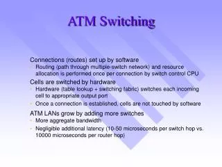
ATM Switching. Connections (routes) set up by software Routing (path through multiple-switch network) and resource allocation is performed once per connection by switch control CPU Cells are switched by hardware

ATM Switching
E N D
Presentation Transcript
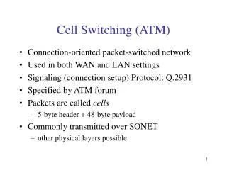
ATM Switching • Connections (routes) set up by software • Routing (path through multiple-switch network) and resource allocation is performed once per connection by switch control CPU • Cells are switched by hardware • Hardware (table lookup + switching fabric) switches each incoming cell to appropriate output port • Once a connection is established, cells are not touched by software • ATM LANs grow by adding more switches • More aggregate bandwidth • Negligible additional latency (10-50 microseconds per switch hop vs. 10000 microseconds per router hop)
ATM Switching: Architectures • Switch fabric architecture is critical because it affects: • aggregate throughput capacity • cell transit delay • cell blocking probabilities • port speeds • complexity of routing tables and switch controller interface • required fabric logic speeds • Many forms and variants of switching architectures are possible; each has advantages and disadvantages
Switching Techniques • Approaches used in implementing switching • Shared Memory approach • A central controller copies cells from the inputs to a shared memory where all outputs have buffers • VP lookup table is used to determine output • Limited to small number of ports for high bandwidth connections
Switching Techniques • Shared medium approach • High Speed bus • Time slot for each input • Inputs visible to all outputs
1 N 1 N Switching Techniques • Space Division Multiplexing • Crossbar type multistage switches
16x16 Matrix Architecture Port 0 Port 1 Port 0 Port 1 Port 2 Port 3 Port 2 Port 3 Port 4 Port 5 Port 4 Port 5 Port 6 Port 7 Port 6 Port 7 Port 8 Port 9 Port 8 Port 9 Port 10 Port 11 Port 10 Port 11 Port 12 Port 13 Port 12 Port 13 Port 14 Port 15 Port 14 Port 15
ATM Switching: Matrix • Advantages • Symmetric structure uses array of identical • elements (potential economies of scale) • Disadvantages • Blocking—probability of losing cells is not zero • Long transit delays—multiple stages require higher logic • speeds (2X) than actual switch throughput capacity • Port speed changes require matrix element changes • Multicast implemented by copying cells
Switching Rates for Shared Memory • L=155Mbps line, 366,000 cells/sec, 2.7usec/cell • fabric must switch at 2LN cells/sec • 8x8 switch 2*366,000*8=5.9Mcells/sec or 2.5 Gbps • 2.5Gbps lines require throughput 40Gbps • cell interval 10nsec • read or write takes 10nsec • clock rate? • What about 1000x1000 switch?
Shared Media • Switching rates half of shared memory • Additional functionality possible
ATM Switching:Contentionless Time Division • Advantages • Non-blocking • Deterministic performance—probability of cell loss = 0 • Flexible port speeds • (DS-1, E-1, DS-3, E-3, 100M, 155M, 622M) • Hardware multicast without increasing fabric cell traffic • Low transit delays • Disadvantages • Limited scalability on single TDM fabric • Use time-space-time to expand
Output vs Input queueing • Head of Line Blocking
Input queueing • 2x2 switch 75% of output • Large switches 59% of maximum • Output queuing cannot be used in some multistage switches
Assumptions: • Bernoulli process for input distribution. • Because we assume an aggregation of sources and a multiplexing buffer. • Probability of a cell arrival at input = p , probability of no cell arrival = 1-p • Assume well mixed inputs with no dominating source …
Output Buffering in Crossbar Crossbar Fabric switching speed would have to be increased N times 1 N 1 N
Output Queueing 1 1 2 2 3 3 Switch Fabric N N
Assumptions • Bernoulli traffic • Probability of arrival at input = p • Input transferred to output = p/N • Switch fabric speed allows for all cells that arrived to be delivered to an output in one cell time
Output queue Different ways we can choose j outputs Probability that j inputs have cells Probability N-j don’t have cells
Example • N=100, p=.98, E(Q)=89 • Utilization is not limited by buffering scheme • Input queueing limited to 0.586 of input rate for large N, .75 for 2X2 switch
Input Queuing • Focus on ith output line • Assume all inputs are saturated (p=1) • At most one of these inputs can pass data to output i • Assuming uniform traffic all inputs are equally likely to have cell for output i • On average, only 0.567 cells will be destined for the ith port at any time. The other cells will suffer from HOL blocking.
1 Knockout Switch Broadcast Bus 1 2 3 N N Disadvantage: N Broadcast Bus
Knockout Switch • Why is the switch called a Knockout Switch? • N bus lines feed into N Bus interfaces • N cells can be transmitted to one output in one cell time with N cell buffers • Unlikely that N cells will all be destined for same output. • Limit number that can be buffered to L
Cell Filter Cell Filter Cell Filter Knockout Continued Broadcast Bus 1 2 N N inputs Concentrator L outputs Shifter L cell buffers Single Output
Knockout analysis • What is the shifter used for? • Maintains FIFO order
Multistage space switches • Goal to reduce N2 switch elements • Build multistage switch with fewer switching elements and a less rich interconnection network • Evaluate in terms of cost and throughput
Three stage networks:Building Block 1 1 1 ... ... n k n 1 k
N/nxN/n kxn n nxk k N/n N/n k n N/n switches k switches N/n switches nxk N/nxN/n kxn n k N/n k n nxk N/nxN/n kxn k N/n n k N/n n 3 stage switch
Connections to each switch in next layer N/nxN/n kxn n nxk k N/n N/n k n N/n switches k switches N/n switches nxk N/nxN/n kxn n k N/n k n nxk N/nxN/n kxn k N/n n k N/n n
Characteristics • Less than N2 for some values of k,n • Blocking: Route may not be available from an input to an output, even though the output is not in use. • Assume N=6, n=2, k=3
Blocking Problem: 1 to 2 0 3x3 2x2 0 2x2 1 1 3 switches 2x2 3x3 2x2 2 2 3 3 2x2 2x2 4 4 N=6, n=2, k=2 5 5
Avoiding Blocking • Desire connection between specific input port and a specific output • Assume the other n-1 inputs are used, each passing through a different level 2 switch • Assume n-1 of the outputs adjacent to the required output are used (n-1of the k inputs to that level 3 switch are used, each coming from a different level 2 switch)
Avoiding Blocking • Worst case • The (n-1) inputs and (n-1) outputs all use different level 2 switches • none of these level 2 switches can be used to route the connection • Since there are k level 2 switches, to avoid blocking, k-2(n-1)>=1, k>=2n-1
N/nxN/n kxn n nxk k N/n N/n k n N/n switches k switches N/n switches nxk N/nxN/n kxn n k N/n k n nxk N/nxN/n kxn k N/n n k N/n n Avoiding Blocking 2(n-1) used
Non-blocking switching elements • k=2n-1 • Count of crosspoint switches C=2(kn)(N/n)+k(N/n)2 =k(2N+N2/n2) • C=(2n-1)(2N+N2/n2) • value of n that minimizes C, n = (N/2)1/2 • In this case, the number of crosspoint switches For N=1024, NxN crossbar C=1,000,000 nopt=23, Cmin=185,000