Download
1 / 26
260 likes | 473 Views
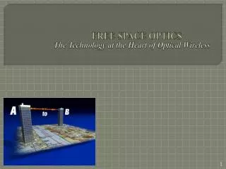
The Technology at the Heart of Optical Wireless. FREE SPACE OPTICS. Imagine a Technology . Simple, cost-efficient high speed connectivity, Work on full duplex, Installed globally, in less than a day license free, Long-range point to point links. FSO - Technology.

E N D
The Technology at the Heart of Optical Wireless FREE SPACE OPTICS
Imagine a Technology Simple, cost-efficient high speed connectivity, Work on full duplex, Installed globally, in less than a day license free, Long-range point to point links.
FSO - Technology Clear line-of-site technology Depended on clear atmosphere Use invisible modulated beams of light instead of radio waves Transmission speed up to 1.25 Gbps They allows communication through windows without the need for rooftop mounted antenna 40 Gbps has been successfully tested in laboratories
Why optical communication? Electro-magnetic frequency spectrum has been gobbled up. The airwaves are becoming severely overcrowded. Little space left in the radio spectrum, to add more information channels. For this reason, many companies and individuals are looking toward light(optical communication).
Features and Benefits Very high data-rates (several Gbps). Small beam divergence minimizes free-space losses. Low power-consumption. Dependence on clear sky. Requires no RF spectrum licensing. Is easily upgradeable. Requires no security software upgrades. Can be deployed behind windows, eliminating the need for costly rooftop rights. Long range point to point links. No cables required. Installed globally & license-free, less than a day.
A receiver at the other end of the link collects the light using lenses and/or mirrors Transmitter projects the carefully aimed light pulses into the air 3 2 Received signal converted back into fiber or copper and connected to the network 4 Network traffic converted into pulses of invisible light representing 1’s and 0’s 1 • Reverse direction data transported the same way. • Full duplex 5 How FSO works? Anything that can be done in fiber can be done with FSO
How FSO works? Conti… Optical wireless unit uses an optical sources + transmitting lens or telescope that transits light through the atmosphere to receiving lens. It transmit invisible, eye-safe light beams form source to destination using low power infrared laser in the THz spectrum. Light focused on highly sensitive detector receives. At this point, the receiving lens or telescope connect with optical cable which gives our original information. Commercially, available systems offer capacities in the range of 100 Mbps to 2.5 Gbps. Most FSO system use simple ON-OFF keying modulation format.
Transceiver Unit • The received laser beam (yellow) is much wider than the transmitted beam (red). That’s why the receiver lens is so much larger than the transmitter lens. • Both lenses, which share the same axis.
Transmission Issues Alignment: FSO systems have to maintain transceivers alignment. Transceivers transmit highly directional and narrow beams of light that must impinge upon the receiver aperture. FSO receivers have a limited cone of acceptance and is similar to the cone of light projected by the transmitter.
Transmission Issues conti… Link equation • Control transmit power, beam divergence, range of link, receiver aperture size. • But can’t control the atmospheric attenuation factor & is roughly independent of wavelength in heavy attenuation condition.
Optical Source • The modulated light source, which is typically a LASER or LED, provides the transmitted optical signal. LASER 1. Modulates at 20 Mbps to 2.5 Gbps 2. Coherent 3. Operate in the 850 to 1550 wavelength band LED 1. Very difficult to modulate high intensity 2. Non coherent 3. Less optical output 4. Less expensive & less complex circuitry 5. Longer lifetime than laser
Optical Detectors PIN photodiodes Inexpensive Sensitive in the red and infrared spectrum Photomultiplier tubes (PMT’s) Expensive Required a high voltage (about 1000 volt) Many types have poor red wavelength sensitivity Avalanche Photodiodes (APD) Expensive Excellent red sensitivity
Lens used in Transceivers • No matter what light source is to be used, it is advantageous to use as large an optical aperture ( lens) as possible in order to maximize optical gain at the receiver end. • Matter that have to be considered, when choosing lens: 1. Cost : goes up exponentially with size. 2. Weight : also goes up exponentially with size, so it is roughly proportional with cost. 3. Fragility : a large, heavy glass lens assembly is seemingly more prone to damage due to handling or accident than a lighter optical assembly. 4. Practicality : if use a larger lens than it is bigger, heavier and harder. The practical alternative to a large glass lens is a molded Fresnel lens. These lenses are flat and, if properly constructed, can have excellent optical characteristics.
Link Budget A link budget is used to predict how much margin, or extra power, will be available in a link under any set of operating conditions. Power budget of a free space link, include the transmit power and all power losses (receive sensitivity, optical system losses, geometric losses, & alignment loss). The remaining power at the receiver largely determines the possible data.
Optical Signal Degradation Fog: • Fog is vapor component of water droplets, which are only a few hundred microns in diameter but can modify light characteristics. • It decrease the power density. Scattering: • It caused when the wavelength collides with the scatterer. • Physical size of the scatterer determines the type of the scattering. 1. Scatterer is smaller than the wavelength = Ray leigh scattering. 2. Scatterer is of comparable size the wavelength = Mie scattering. 3. Scatterer is much larger than the wavelength = Non-selective scattering • There is no loss of energy, only a directional redistribution of energy.
Optical Signal Degradation conti… Physical obstructions: Flying birds of construction cranes can temporarily blocks a signal beam, but this tends to cause only short interruptions, and transmissions are easily and automatically resumed. Building sway: The movement of the building can upset transmitter and receiver alignment, due to earthquake or heavy vehicles’ jerks. Scintillation: It is inhomogeneties in Temp. and Pressure. It change index of optical reflection and reduce the velocity of light beam & light intensity.
Optical Signal Degradation conti… Window attenuation: • Using window communication, windows allow optical signals to pass through them, they all add some amount of attenuation to the signal. • Uncoated glass windows usually less attenuate & coated glass windows have much greater attenuation.
Optical Signal Degradation conti… • Another limitation of light beam communication is that since light can’t penetrate trees, hills or building.
Application Deep space communications; distances measured in light-years Building to building computer data links; very high data rates. Telemetry transmitters from remote monitors; weather, geophysical. Optical radar; shape, speed, direction and range. Remote telephone links; cheaper than microwave. Metro network extensions. Campus wide computer networks City-wide information broadcasting Inter-office data links Computer to printer links
Space Application • Transmission between different earth- orbiting satellites. • Data can also be exchanged between a more remote spacecraft and a station on or near Earth.
Free Space Path Loss • Spreading out of electromagnetic energy in free space. • Receiving antenna’s aperture.
Losses • Geometric losses are those losses that occur due to the spreading of the transmitted beam between the transmitter and the receiver. Typically, the beam spreads to a size larger than the receive aperture, and this “overfill” energy is lost. In general, larger receive apertures or smaller transmit divergences result in less geometric loss for a given range. • Mis-point loss or alignment loss represents the imperfect alignment of the transmitter and the receiver
Security Security is a major consideration on just about any wireless project these days. Even though Free-Space Optics is a wireless technology it does not have the nasty habit of broadcasting to anybody and everybody. It transmits a very high frequency narrow beam of light to a specific destination.
Conclusion It give very high data rate. Very cheaper than fiber optic communication. Can be deployed behind windows, if rooftop sites are costly. Also used for temporary connection. Give more information security than other technology, requires no security software. But, depending on the geographical location.
REFERENCES • www.ieeexplore.ieee.org • www.opticalcommunication.com • http://en.wikipedia.org/wiki/Free-space_path_loss • http://www.freespaceoptics.com • http://www.cablefreesolutions.com/index.htm • http://www.freespaceoptics.org • Electronics for you - magazine • Optical space communication – by Franz, J. • Study on space optical communication – by Jain V.K. • Understanding the performance of free-space optics. -- by Scott Bloom, Eric Korevaar, John Schuster, Heinz Willebrand (June 2003 / Vol. 2, No. 6 / journal of optical networking)