Download
1 / 14
140 likes | 286 Views
Optimality Study of Logic Synthesis for LUT-Based FPGAs. Jason Cong and Kirill Minkovich. Terms Purpose How the Examples were constructed Compare their structure to existing benchmarks Look at the results. Outline. LEKO – Logic Synthesis examples with Known Optimal

E N D
Optimality Study of Logic Synthesis for LUT-Based FPGAs Jason Cong and KirillMinkovich
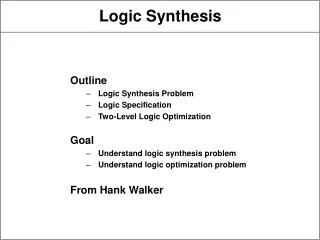
Terms • Purpose • How the Examples were constructed • Compare their structure to existing benchmarks • Look at the results Outline
LEKO – Logic Synthesis examples with Known Optimal • LEKU – Logic Synthesis examples with Known Upper bounds • MCNC – Microelectronics Center of North Carolina • MFFC – Maximum Fanout Free Cone (a method of measuring the structure of the circuit) Terms
To develop an algorithm for generating synthetic benchmarks (LEKO and LEKU) with known optimal technology mapping solutions • Allow us to construct arbitrarily large test circuits for Synthesis software • To show that these benchmarks are structurally similar the MCNC benchmark • Show results Purpose
Basic Building Block – Core Graph (Cn): • It has n inputs and n outputs • Every output is a function of all n inputs • Each internal node of Cn has exactly 2 inputs • There exists an optimal mapping (area/depth) of Cn into a 4-LUT mapping solution • These *same* building blocks are put together on several layers so that there exist a path from every Basic block on the bottom layer to the top layer. LEKO Construction
To construct a core graph from a pre-existing benchmark, all you have to do is extract a piece of logic from that has an equal number of inputs and outputs • LEKU circuits are derived from the LEKO circuits by collapsing and gate decomposition Additional Notes
Only performed the logic synthesis step of the tools and did not go through the final placement and routing • The actual depths are not report because Xilinx uses two 4-LUTS in their logic blocks Important notes about the results
Mapping Results (LEKO) Synthesis Results (LEKU) Results
This suggests that there may be significant opportunity for improvement in the logic-synthesis algorithms. • They must have a more global view of synthesis including duplication removal. Results (2)
The problems with the MCNC is that almost every logic-synthesis tool is specifically tuned to perform well on these benchmarks. • LEKO allows the designer to combine multiple ‘hard to map’ cares into one design with a known optimal • Knowing the optimal solution, the designer can see exactly where the algorithm made the mistake and why Conclusions
LEKU circuits are meant to test how the existing algorithms perform and how much room is left for improvement when handling each type of inefficiency and/or redundancy. • This is basically a platform to create new benchmarks that can test every part of a synthesis tool Conclusions (2)