Download
1 / 26
260 likes | 450 Views
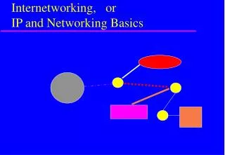
IP and Networking Basics. Selection of slides taken from Internet Society Workshop Resource Centre: http:// ws.edu.isoc.org /data/2010/15678359774b67528c8924a/lecture-01-mon-tue-addressing-ios.pdf. A small internetwork or (small “i”) “internet”. The principle of “Internetworking”.

E N D
IP and Networking Basics Selection of slides taken from Internet Society Workshop Resource Centre: http://ws.edu.isoc.org/data/2010/15678359774b67528c8924a/lecture-01-mon-tue-addressing-ios.pdf
The principle of “Internetworking” • We have lots of little networks • Many different owners/operators • Many different types • Ethernet, dedicated leased lines, dialup, optical, broadband, wireless, ... • Each type has its own idea of low level addressing and protocols • We want to connect them all together and provide a unified view of the whole lot (treat the collection of networks as a single large internetwork)
millions of connected computing devices: hosts, end-systems PC’s workstations, servers PDA’s phones, toasters running network apps communication links fiber, copper, radio, satellite routers: forward packets (chunks) of data through network What’s the Internet: “nuts and bolts” view router workstation server mobile local ISP regional ISP company network
What’s the Internet: “nuts and bolts” view • protocols: control sending, receiving of messages • e.g., TCP, IP, HTTP, FTP, PPP • Internet: “network of networks” • loosely hierarchical • public Internet versus private intranet • Internet standards • RFC: Request for comments • IETF: Internet Engineering Task Force router workstation server mobile local ISP regional ISP company network
What’s the Internet: a service view • communication infrastructure enables distributed applications: • WWW, email, games,e-commerce, database, e-voting, more? • communication services provided: • connectionless • connection-oriented router workstation server mobile local ISP regional ISP company network
Application 7 Presentation 6 Session 5 Transport 4 Network 3 Data Link 2 Physical 1 The OSI Model Upper Layers Application oriented “End-to-End”-Layers Lower Layers Network oriented “Hop-by-hop” layers
Why layering? • Dealing with complex systems: • explicit structure allows identification, relationship of complex system’s pieces • layered reference model for discussion • modularization eases maintenance, updating of system • change of implementation of layer’s service transparent to rest of system • e.g., change in gate procedure does not affect rest of system
SMTP HTTP FTP Telnet DNS Audio Video TCP UDP RTP IP Ethernet ATM Optics ADSL 3G PPP Satellite The IP Hourglass Model Application layer Transport layer Network layer Physical and Data link layer
Application Application TCP or UDP TCP or UDP IP IP IP IP Link Link Link Link Link Link Physical Physical Physical Layer Interaction:TCP/IP Model End to end Hop by hop Router Host Host Router
End-to-end layers • Upper layers are “end-to-end” • Applications at the two ends behave as if they can talk directly to each other • They do not concern themselves with the details of what happens in between
Hop-by-hop layers • At the lower layers, devices share access to the same physical medium • Devices communicate directly with each other • The network layer (IP) has some knowledge of how many small networks are interconnected to make a large internet • Information moves one hop at a time, getting closer to the destination at each hop
Application Application TCP or UDP TCP or UDP IP IP IP IP Link Link Link Link Link Link Physical Physical Physical Layer Interaction:TCP/IP Model Router Host Host Router
Application Application TCP or UDP TCP or UDP IP IP IP IP Link Link Link Link Link Link Physical Physical Physical Layer Interaction:The Application Layer Applications behave as if they can talk to each other, but in reality the application at each side talks to the TCP or UDP service below it. The application layer doesn't care about what happens at the lower layers, provided the transport layer carries the application's data safely from end to end. Router Host Host Router
Application Application TCP or UDP TCP or UDP IP IP IP IP Link Link Link Link Link Link Physical Physical Physical Layer Interaction:The Transport Layer The transport layer instances at the two ends act as if they are talking to each other, but in reality they are each talking to the IP layer below it. The transport layer doesn't care about what the application layer is doing above it. The transport layer doesn't care what happens in the IP layer or below, as long as the IP layer can move datagrams from one side to the other. Router Host Host Router
Application Application TCP or UDP TCP or UDP IP IP IP IP Link Link Link Link Link Link Physical Physical Physical Layer Interaction:The Network Layer (IP) The IP layer has to know a lot about the topology of the network (which host is connected to which router, which routers are connected to each other), but it doesn't care about what happens at the upper layers. The IP layer works forwards messages hop by hop from one side to the other side. Router Host Host Router
Application Application TCP or UDP TCP or UDP IP IP IP IP Link Link Link Link Link Link Physical Physical Physical Layer Interaction:Link and Physical Layers The link layer doesn't care what happens above it, but it is very closely tied to the physical layer below it. All links are independent of each other, and have no way of communicating with each other. Router Host Host Router
application transport network link physical network link physical application transport network link physical data data application transport network link physical application transport network link physical Layering: physical communication
Frame, Datagram, Segment, Packet • Different names for packets at different layers • Ethernet (link layer) frame • IP (network layer) datagram • TCP (transport layer) segment • Terminology is not strictly followed • we often just use the term “packet” at any layer
Lower layers add headers (and sometimes trailers) to data from higher layers Encapsulation & Decapsulation Data Application Header Transport Layer Data Transport Header Network Layer Data Network Header Header Data Network Trailer Header Link Layer Data Data Link Header Header Header Data Trailer Data Link
Preamble Dest Source Type Data CRC Layer 2 - Ethernet frame • Destination and source are 48-bit MAC addresses (e.g., 00:26:4a:18:f6:aa) • Type 0x0800 means that the “data” portion of the Ethernet frame contains an IPv4 datagram. Type 0x0806 for ARP. Type 0x86DD for IPv6. • “Data” part of layer 2 frame contains a layer 3 datagram. 6 bytes 6 bytes 2 bytes 46 to 1500 bytes 4 bytes
Protocol = 6 means data portion contains a TCP segment. Protocol = 17 means UDP. Version IHL Differentiated Services Total Length Identification Flags Fragment Offset Time to Live Protocol Header Checksum Source Address (32-bit IPv4 address) Destination Address (32-bit IPv4 address) Options Padding Data (contains layer 4 segment) Layer 3 - IPv4 datagram • Version = 4If no options, IHL = 5Source and Destination are 32-bit IPv4 addresses
32 bit number (4 octet number):(e.g. 133.27.162.125) Decimal Representation: Binary Representation: Hexadecimal Representation: 133 27 162 125 10000101 00011011 10100010 01111101 85 1B A2 7D Basic Structure of an IPv4 Address
Source and Destination are 16-bit TCP port numbers (IP addresses are implied by the IP header) If no options, Data Offset = 5 (which means 20 octets) Source Port Destination Port Sequence Number Acknowledgement Number Data Offset Reserved URG ACK EOL RST SYN FIN Window Checksum Urgent Pointer Options Padding Data (contains application data) Layer 4 - TCP segment
The need for Packet Forwarding • Many small networks can be interconnected to make a larger internetwork • A device on one network cannot send a packet directly to a device on another network • The packet has to be forwarded from one network to another, through intermediate nodes, until it reaches its destination • The intermediate nodes are called “routers”