Verilog 2 - Design Examples
450 likes | 653 Views
Verilog 2 - Design Examples. 6.375 Complex Digital Systems Arvind February 9, 2009. Verilog can be used at several levels. A common approach is to use C/C++ for initial behavioral modeling, and for building test rigs. High-Level Behavioral. Register Transfer Level.

Verilog 2 - Design Examples
E N D
Presentation Transcript
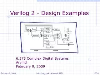
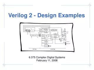
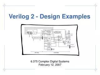
Verilog 2 - Design Examples 6.375 Complex Digital Systems Arvind February 9, 2009 http://csg.csail.mit.edu/6.375/
Verilog can be used at several levels A common approach is to use C/C++ for initial behavioral modeling, and for building test rigs High-Level Behavioral Register Transfer Level automatic tools to synthesize a low-level gate-level model Gate Level http://csg.csail.mit.edu/6.375/
Guidelines for writing synthesizable Verilog • Combinational logic: • Use continuous assignments (assign) assign C_in = B_out + 1; • Use always@(*) blocks with blocking assignments (=) always @(*) begin out = 2’d0; if (in1 == 1) out = 2’d1; else if(in2 == 1) out = 2’d2; end • Sequential logic: • Use always @(posedge clk) and non-blocking assignments (<=) always @( posedge clk ) C_out <= C_in; • Use only positive-edge triggered flip-flops for state • Do not assign the same variable from more than one always block • Only leaf modules should have functionality; use higher-level modules only for wiring together sub-modules http://csg.csail.mit.edu/6.375/
A B C +1 +1 An example wire A_in, B_in, C_in; reg A_out, B_out, C_out; always @( posedge clk ) begin A_out <= A_in; B_out <= B_in; C_out <= C_in; end assign B_in = A_out + 1; assign C_in = B_out + 1; The order of non-blocking assignments does not matter! http://csg.csail.mit.edu/6.375/
Another style – multiple always blocks wire A_in, B_in, C_in; reg A_out, B_out, C_out; always @( posedge clk ) A_out <= A_in; assign B_in = A_out + 1; always @( posedge clk ) B_out <= B_in; assign C_in = B_out + 1; always @( posedge clk ) C_out <= C_in; A B C +1 +1 Does it have the same functionality? Yes. But why? Need to understand something about Verilog execution semantics http://csg.csail.mit.edu/6.375/
A B C +1 +1 +1 +1 Yet another style – blocking assignments wire A_in, B_in, C_in; reg A_out, B_out, C_out; always @( posedge clk ) begin A_out = A_in; B_out = B_in; C_out = C_in; end assign B_in = A_out + 1; assign C_in = B_out + 1; Does it have the same functionality? Not even close! http://csg.csail.mit.edu/6.375/
Verilog execution semantics - Driven by simulation - Explained using event queues http://csg.csail.mit.edu/6.375/
C A B Execution semantics of Verilog - 1 wire A_in, B_in, C_in; reg A_out, B_out, C_out; always @( posedge clk ) A_out <= A_in; assign B_in = A_out + 1; always @( posedge clk ) B_out <= B_in; assign C_in = B_out + 1; always @( posedge clk ) C_out <= C_in; Active Event Queue A 1 B On clock edge all those events which are sensitive to the clock are added to the active event queue in any order! 2 C http://csg.csail.mit.edu/6.375/
C C A B B 1 Execution semantics of Verilog - 2 wire A_in, B_in, C_in; reg A_out, B_out, C_out; always @( posedge clk ) A_out <= A_in; assign B_in = A_out + 1; always @( posedge clk ) B_out <= B_in; assign C_in = B_out + 1; always @( posedge clk ) C_out <= C_in; Active Event Queue A 1 A evaluates and as a consequence 1 is added to the event queue B 2 C http://csg.csail.mit.edu/6.375/
C B 2 1 1 C Execution semantics of Verilog -3 wire A_in, B_in, C_in; reg A_out, B_out, C_out; always @( posedge clk ) A_out <= A_in; assign B_in = A_out + 1; always @( posedge clk ) B_out <= B_in; assign C_in = B_out + 1; always @( posedge clk ) C_out <= C_in; Active Event Queue A 1 B evaluates and as a consequence 2 is added to the event queue Event queue is emptied before we go to next clock cycle B 2 C http://csg.csail.mit.edu/6.375/
Non-blocking assignment • Within a “clock cycle” all RHS variables are read first and all the LHS variables are updated together at the end of the clock cycle • Consequently, two event queues have to be maintained – one keeps the computations to be performed while the other keeps the variables to be updated http://csg.csail.mit.edu/6.375/
2 1 Non-blocking assignments require two event queues wire A_in, B_in, C_in; reg A_out, B_out, C_out; always @( posedge clk ) A_out <= A_in; assign B_in = A_out + 1; always @( posedge clk ) B_out <= B_in; assign C_in = B_out + 1; always @( posedge clk ) C_out <= C_in; Active Event Queue C R B R A R A 1 Non-Blocking Queue B C L B L A L 2 Variables in RHS of always blocks are not updated until all inputs (e.g. LHS + dependencies) are evaluated C http://csg.csail.mit.edu/6.375/
A B C +1 +1 +1 +1 Blocking assignments have a sequential language like semantics wire A_in, B_in, C_in; reg A_out, B_out, C_out; always @( posedge clk ) begin A_out = A_in; B_out = B_in; C_out = C_in; end assign B_in = A_out + 1; assign C_in = B_out + 1; http://csg.csail.mit.edu/6.375/
Behavioral Verilog is richer • Characterized by heavy use of sequential blocking statements in large always blocks • Many constructs are not synthesizable but can be useful for behavioral modeling and test benches • Data dependent for and while loops • Additional behavioral datatypes: integer, real • Magic initialization blocks: initial • Magic delay statements: #<delay> • System calls:$display, $assert, $finish http://csg.csail.mit.edu/6.375/
System calls for test harnesses and simulation reg [ 1023:0 ] exe_filename; initial begin // This turns on VCD (plus) output $vcdpluson(0); // This gets the program to load into memory from the // command line if ( $value$plusargs( "exe=%s", exe_filename ) ) $readmemh( exe_filename, mem.m ); else begin $display( "ERROR: No executable specified! (use +exe=<filename>)" ); $finish; end // Stobe reset #0 reset = 1; #38 reset = 0; end http://csg.csail.mit.edu/6.375/
Verilog Design Examples • Greatest Common Divisor • Unpipelined SMIPSv1 processor http://csg.csail.mit.edu/6.375/
GCD in C int GCD( int inA, int inB) { int done = 0; int A = inA; int B = inB; while ( !done ) { if ( A < B ) { swap = A; A = B; B = swap; } else if ( B != 0 ) A = A - B; else done = 1; } return A; } Such a GCD description can be easily written in Behavioral Verilog It can be simulated but it will have nothing to do with hardware, i.e. it won’t synthesize. http://csg.csail.mit.edu/6.375/
Behavioral GCD in Verilog module gcdGCDUnit_behav#( parameter W = 16 ) ( input [W-1:0] inA, inB, output [W-1:0] out ); reg[W-1:0] A, B, out, swap; integer done; always @(*) begin done = 0; A = inA; B = inB; while ( !done ) begin if ( A < B ) swap = A; A = B; B = swap; else if ( B != 0 ) A = A - B; else done = 1; end out = A; end endmodule User sets the input operands and checks the output; the answer will appear immediately, like a combinational circuit Note data dependent loop, “done” http://csg.csail.mit.edu/6.375/
Some dangers in writing behavioral models module exGCDTestHarness_behav; reg [15:0] inA, inB; wire [15:0] out; exGCD_behav#(16) gcd_unit(.inA(inA), .inB(inB), .out(out)); initial begin // 3 = GCD( 27, 15 ) inA = 27; inB = 15; #10; if (out == 3) $display("Test gcd(27,15) succeeded, [%x==%x]", out, 3); else $display("Test gcd(27,15) failed, [%x != %x]", out, 3); $finish; end endmodule without some delay out is bogus http://csg.csail.mit.edu/6.375/
State Less-Than Comparator Equal Comparator Subtractor Deriving an RTL model for GCD module gcdGCDUnit_behav#( parameter W = 16 ) ( input [W-1:0] inA, inB, output [W-1:0] out ); reg[W-1:0] A, B, out, swap; integer done; always @(*) begin done = 0; A = inA; B = inB; while ( !done ) begin if ( A < B ) swap = A; A = B; B = swap; else if ( B != 0 ) A = A - B; else done = 1; end out = A; end endmodule What does the RTL implementation need? http://csg.csail.mit.edu/6.375/
input_available result_rdy idle result_taken operand_A result_data operand_B clk reset Step 1: Design an appropriate port interface http://csg.csail.mit.edu/6.375/
zero? lt A sub Step 2: Design a datapath which has the functional units A = inA; B = inB; while ( !done ) begin if ( A < B ) swap = A; A = B; B = swap; else if (B != 0) A = A - B; else done = 1; End Y = A; B http://csg.csail.mit.edu/6.375/
A sel A en B sel B en B=0 A<B zero? lt A sub Step 3: Add the control unit to sequence the datapath Control unit should be designed to be either busy or waiting for input or waiting for output to be picked up A = inA; B = inB; while ( !done ) begin if ( A < B ) swap = A; A = B; B = swap; else if (B != 0) A = A - B; else done = 1; End Y = A; B http://csg.csail.mit.edu/6.375/
A sel A en B sel B en B = 0 A < B zero? lt A sub B Datapath module interface module gcdGCDUnitDpath_sstr#( parameter W = 16 ) ( input clk, // Data signals input[W-1:0]operand_A, input [W-1:0]operand_B, output [W-1:0] result_data, // Control signals (ctrl->dpath) input A_en, input B_en, input[1:0] A_sel, input B_sel, // Control signals (dpath->ctrl) output B_zero, output A_lt_B ); http://csg.csail.mit.edu/6.375/
A sel A en B sel B en B = 0 A < B zero? lt A sub B Connect the modules wire [W-1:0] B; wire [W-1:0] sub_out; wire [W-1:0] A_out; vcMux3#(W) A_mux ( .in0 (operand_A), .in1 (B), .in2 (sub_out), .sel (A_sel), .out (A_out) ); wire [W-1:0] A; vcEDFF_pf#(W) A_pf ( .clk (clk), .en_p (A_en), .d_p (A_out), .q_np (A) ); http://csg.csail.mit.edu/6.375/
Using explicit state helps eliminate issues with non-blocking assignments Continuous assignment combinational logic is fine Connect the modules ... wire [W-1:0] B_out; vcMux2#(W) B_mux ( .in0 (operand_B), .in1 (A), .sel (B_sel), .out (B_out) ); vcEDFF_pf#(W) B_pf ( .clk (clk), .en_p (B_en), .d_p (B_out), .q_np (B) ); assign B_zero = (B==0); assign A_lt_B = (A < B); assign sub_out = A - B; assign result_data = A; wire [W-1:0] B; wire [W-1:0] sub_out; wire [W-1:0] A_out; vcMux3#(W) A_mux ( .in0 (operand_A), .in1 (B), .in2 (sub_out), .sel (A_sel), .out (A_out) ); wire [W-1:0] A; vcEDFF_pf#(W) A_pf ( .clk (clk), .en_p (A_en), .d_p (A_out), .q_np (A) ); http://csg.csail.mit.edu/6.375/
Control unit requires a state machine for valid/ready signals reset WAIT Waiting for new input operands input_availble CALC Swapping and subtracting ( B = 0 ) DONE Waiting for consumer to take the result result_taken http://csg.csail.mit.edu/6.375/
Implementing the control logic FSM in Verilog localparam WAIT = 2'd0; localparam CALC = 2'd1; localparam DONE = 2'd2; reg [1:0] state_next; wire [1:0] state; vcRDFF_pf#(2,WAIT) state_pf ( .clk (clk), .reset_p (reset), .d_p (state_next), .q_np (state) ); Localparams are not really parameters at all. They are scoped constants. Explicit state in the control logic is also a good idea! http://csg.csail.mit.edu/6.375/
WAIT: begin A_sel = A_SEL_IN; A_en = 1'b1; B_sel = B_SEL_IN; B_en = 1'b1; input_available = 1'b1; end CALC: if ( A_lt_B ) A_sel = A_SEL_B; A_en = 1'b1; B_sel = B_SEL_A; B_en = 1'b1; else if ( !B_zero ) A_sel = A_SEL_SUB; A_en = 1'b1; end DONE: result_rdy = 1'b1; Control signals for the FSM reg [6:0] cs; always @(*) begin //Default control signals A_sel = A_SEL_X; A_en = 1'b0; B_sel = B_SEL_X; B_en = 1'b0; input_available = 1'b0; result_rdy = 1'b0; case ( state ) WAIT : ... CALC : ... DONE : ... endcase end http://csg.csail.mit.edu/6.375/
reset WAIT input_availble CALC ( B = 0 ) DONE result_taken FSM state transitions always @(*) begin // Default is to stay in the same state state_next = state; case ( state ) WAIT : if ( input_available ) state_next = CALC; CALC : if ( B_zero ) state_next = DONE; DONE : if ( result_taken ) state_next = WAIT; endcase end http://csg.csail.mit.edu/6.375/
RTL test harness requires proper handling of the ready/valid signals Generic Test Source Generic Test Sink A sel A en B sel B en B = 0 A < B zero? lt A sub B http://csg.csail.mit.edu/6.375/
Correctness: Compare behavioral and RTL implementations Test Inputs Behavioral Model RTL Model Test Outputs Test Outputs Identical? http://csg.csail.mit.edu/6.375/
Verilog Design Examples • Greatest Common Divisor • Unpipelined SMIPSv1 processor http://csg.csail.mit.edu/6.375/
SMIPS is a simple MIPS ISA which includes three variants • SMIPSv1 • 5 instructions • No exceptions/interrupts • Lecture examples • SMIPSv2 • 35 instructions • No exceptions/interrupts • ISA for lab assignments • SMIPSv3 • 58 instructions • Full system coproc with exceptions/Interrupts • Optional ISA for projects http://csg.csail.mit.edu/6.375/
SMIPSv1 ISA http://csg.csail.mit.edu/6.375/
First step: Design a port interface http://csg.csail.mit.edu/6.375/
Identify memories, datapaths, and random logic Step 1: Identify the memories Step 2: Identify the datapaths Step 3: Everything else is random logic http://csg.csail.mit.edu/6.375/
Identify the signals to interface with the controller http://csg.csail.mit.edu/6.375/
SMIPSv1 datapath module smipsProcDpath_pstr ( input clk, reset, // Memory ports output [31:0] imemreq_addr, output [31:0] dmemreq_addr, output [31:0] dmemreq_data, input [31:0] dmemresp_data, // Controls signals (ctrl->dpath) input pc_sel, input [ 4:0] rf_raddr0, input [ 4:0] rf_raddr1, input rf_wen, input [ 4:0] rf_waddr, input op0_sel, input op1_sel, input [15:0] inst_imm, input wb_sel, // Control signals (dpath->ctrl) output branch_cond_eq, output [7:0] tohost_next ); wire [31:0] branch_targ; wire [31:0] pc_plus4; wire [31:0] pc_out; vcMux2#(32) pc_mux ( .in0 (pc_plus4), .in1 (branch_targ), .sel (pc_sel), .out (pc_out) ); wire [31:0] pc; vcRDFF_pf#(32,32'h0001000) pc_pf ( .clk (clk), .reset_p (reset), .d_p (pc_out), .q_np (pc) ); assign imemreq_addr = pc; vcInc#(32,32'd4) pc_inc4 ( .in (pc), .out (pc_plus4) ); http://csg.csail.mit.edu/6.375/
Register file with 2 combinational read ports and 1 write port module smipsProcDpathRegfile ( input clk, input[ 4:0] raddr0, // Read 0 address (combinational input) output[31:0] rdata0, // Read 0 data (combinational on raddr) input[ 4:0] raddr1, // Read 1 address (combinational input) output[31:0] rdata1, // Read 1 data (combinational on raddr) input wen_p, // Write enable (sample on rising clk edge) input[ 4:0] waddr_p, // Write address(sample on rising clk edge) input [31:0] wdata_p // Write data (sample on rising clk edge)); // We use an array of 32 bit register for the regfile itself reg[31:0] registers[31:0]; // Combinational read ports assign rdata0 = ( raddr0 == 0 ) ? 32'b0 : registers[raddr0]; assign rdata1 = ( raddr1 == 0 ) ? 32'b0 : registers[raddr1]; // Write port is active only when wen is asserted always @( posedge clk ) if ( wen_p && (waddr_p != 5'b0) ) registers[waddr_p] <= wdata_p; endmodule http://csg.csail.mit.edu/6.375/
Verilog for SMIPSv1 control logic `defineLW 32'b100011_?????_?????_?????_?????_?????? `defineSW 32'b101011_?????_?????_?????_?????_?????? `defineADDIU 32'b001001_?????_?????_?????_?????_?????? `defineBNE 32'b000101_?????_?????_?????_?????_?????? localparam cs_sz = 8; reg [cs_sz-1:0] cs; always @(*) begin cs = {cs_sz{1'b0}}; casez ( imemresp_data ) // op0 mux op1 mux wb mux rfile mreq mreq tohost // br type sel sel sel wen r/w val en `ADDIU: cs ={br_pc4, op0_sx, op1_rd0, wmx_alu, 1'b1, mreq_x, 1'b0, 1'b0}; `BNE : cs ={br_neq, op0_sx2, op1_pc4, wmx_x, 1'b0, mreq_x, 1'b0, 1'b0}; `LW : cs ={br_pc4, op0_sx, op1_rd0, wmx_mem, 1'b1, mreq_r, 1'b1, 1'b0}; `SW : cs ={br_pc4, op0_sx, op1_rd0, wmx_x, 1'b0, mreq_w, 1'b1, 1'b0}; `MTC0 : cs ={br_pc4, op0_x, op1_x, wmx_x, 1'b0, mreq_x, 1'b0, 1'b1}; endcase end casez performs simple pattern matching and can be very useful when implementing decoders http://csg.csail.mit.edu/6.375/
Verilog for SMIPSv1 control logic // Set the control signals based on the decoder output wire br_type = cs[7]; assign pc_sel = ( br_type == br_pc4 ) ? 1'b0 : ( br_type == br_neq ) ? ~branch_cond_eq : 1'bx; assign op0_sel = cs[6]; assign op1_sel = cs[5]; assign wb_sel = cs[4]; assign rf_wen = ( reset ? 1'b0 : cs[3] ); assign dmemreq_rw = cs[2]; assign dmemreq_val = ( reset ? 1'b0 : cs[1] ); wire tohost_en = ( reset ? 1'b0 : cs[0] ); // These control signals we can set directly from the instruction bits assign rf_raddr0 = inst[25:21]; assign rf_raddr1 = inst[20:16]; assign rf_waddr = inst[20:16]; assign inst_imm = inst[15:0]; // We are always making an imemreq assign imemreq_val = 1'b1; http://csg.csail.mit.edu/6.375/
Take away points • Follow the simple guidelines to write synthesizable Verilog • Parameterized models provide the foundation for reusable libraries of components • Use explicit state to prevent unwanted state inference and to more directly represent the desired hardware • Begin your RTL design by identifying the external interface and then move on to partition your design into the memories, datapaths, and control logic http://csg.csail.mit.edu/6.375/