Download
1 / 20
200 likes | 362 Views
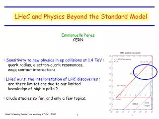
LHeC Test Facility Meeting. OptiM - Computer code for linear and non-linear optics calculations. Alessandra Valloni, Thursday 18.10.2012. Outline. What does OptiM compute ? Input language description Why do we use OptiM? ERL-LHeC schematic layout

E N D
LHeC Test Facility Meeting OptiM - Computer code for linear and non-linear optics calculations Alessandra Valloni, Thursday 18.10.2012
Outline • What does OptiM compute? • Input language description • Why do we use OptiM? ERL-LHeC schematic layout • Example of an input file: lattice for LHeC Recirculating Linear Accelerator Complex • OptiM for the LHeC Test Facility lattice design • Future works and questions
What Does Optim compute? OptiM - Computer code for linear and non-linear optics calculations - OptiM is aimed to assist with linear optics designof particle accelerators (calculations are based on 6x6 transfer matrices) but it is also quite proficient with non-linear optics, tracking and with linear effects due to space charge - It computes the dispersion and betatron functions (for both uncoupled and X-Y coupled particle motions), as well as the beam sizes, the betatron phase advances, etc. The values can be plotted or printed along machine circumference or computed at the end of lattice or at any element - It can also fit parametersof accelerator elements to get required optics functions - It offers a wide choice of elements that allows designing both circular and linear accelerators, along with recirculators - It can perform computations not only at the reference orbit but also at a closed orbit excited by machine errors, correctors or energy offset. In this case the program first finds a new "reference" orbit then expends nonlinear terms for machine elements and then performs computations. That allows one to perform both linear optics computations and non-linear tracking relative to this new orbit
Optim peculiarities • 6D computations: - large set of optics elements • - x-y coupling, acceleration (focusing in cavities is taken into account) • Similar to MAD but has integrated GUI • Can generate MAD and MADX files from OptiM files • It has been used for Optics support of the following machines: • - Jefferson lab (CEBAF – optics redesign, analysis of optics measurements…) • - Fermilab(optics redesign, analysis of optics measurements. Completely done files • for rings, Tevatron, Debuncher, Transfer lines, Electron cooler) • Works on MS-Windows only (No GUI version can be used at any platform) • Written on BC++, the platform which is not supported anymore • Non-linearities are ignored for the combined function magnet (dipole with gradient)
Input file description • math header : numeric and text variables • INPUT PARAMETERS : initial beam energy and the particle mass in MeV, horizontal and vertical beam emittances, relative momentum spreadat the start of the lattice (these values are used for beam envelope calculations and are modified in the course of beam acceleration to take into account the adiabatic damping; effects of the energy spread change due to longitudinal focusing of bunch with finite length are neglected), horizontal and vertical beta-functions, their negative half derivatives at the start of the lattice, initial betatron phases Qx and Qy(these two parameters are ignored in all calculations except printing of Twiss-functions), horizontal and vertical dispersions and their derivativesat the start of the lattice, position and angleof the beam trajectoryat the start of the lattice • block making references to external files : e.g. description of field in accelerating cavity • LATTICE DESCRIPTION : order of the elements in the lattice • LIST BLOCK: list of elements with their parameters • service blocks : Fitting block, (Fitting-Betas), 4D Beta-functions block (Beta-functions block), Space Charge Block (Space Charge Menu) and Trajectory Parameters Block (see Trajectory)
Recirculating Linear Accelerator Complex : Schematic Layout RECIRCULATOR COMPLEX 1) 0.5 Gev injector 2) A pair of 721.44 MHz SCRF linacs with energy gain 10 GeV per pass 3) Six 180° arcs, each arc 1 km radius 4) Re-accelerating stations to compensate energy lost by SR 5) Switching stations at the beginning and end of each linac to combine the beams from different arcs and to distribute them over different arcs (Spreaders/Combiners) 6) Matching optics 7) Extraction dump at 0.5 GeV
LINAC LAYOUT in OPTIM: Lattice description (1/3) • LATTICE DESCRIPTION : • order of the elements in the lattice 18 UNITS * 56m/UNIT = 1008m 1 1 13.4 0.1 0.1 0.1 13.4 13.4 13.4 0.1 56 m
LINAC LAYOUT in OPTIM: Lattice description (2/3) ? ? 1 Cryomodule 8 cavities In 1 UNIT 4 Cryos 32 cavities $ΔE = energy gain per cavity = 17.36 MeV $E00 = 500MeV (Injection Energy) Energy gain/half unit : $E01 = $E00 +16 *$DE*cos($Fi) 10 GeV Linac 1 : 500 MeV 10500 MeV for the first pass
LINAC LAYOUT in OPTIM: Lattice description(3/3) Gradient scaling Betatron phase advance per cell of 1300along the entire linac This requires scaling up of the quadrupole field gradients with energy ( to assure constant value of k Q=0.361
fitting of beta-functions, dispersion and momentum compaction The program uses the steepest descend method with automatically chosen step. The initial values of steps for length, magnetic field and its gradient are determined here Required parameters and their accuracy. To calculate the fitting error (which is minimized in the course of the fitting) the program uses the accuracy parameters for each of fitting parameters Elements can be organized in groups so that the elements in each group are changed proportionally during fitting
Optim output 1300 1 unit = 56m 1 unit = 56m
ARC OPTICS Layout in Optim(1/2) MATH HEADER : numeric variables and calculation Arc Radius = 1km Cell number = 60 Arc Length = 3.14159km Cell Length =52.35m Total number of dipoles = 600 Quad singlet + 5 Dipoles + Quads triplet + 5 Dipoles Dipole Length = 4m 1 cell B=p/(ρc)
ARC OPTICS Layout in Optim (2/2) Quad singlet + 5 Dipoles + Quads triplet + 5 Dipoles 1 cell 150 1.5 BETA_X&Y[m] DISP_X&Y[m] 52.3599 0
beam dynamics challenges for the LHeC ERL which could be studied at the test facility SCL2 • Multi-pass ERL optics tuning • Recirculative Beam Break Up • Ion accumulation, ion instabilities and ion clearing (?) • Electron beam stability in view of proton emittance growth (?) Dump 150-300 MeV ERL Layout 4 x 5 cell, 721 MHz SCL1 5 MeV Injector ~6.5 m
LINAC : Half Cryo Module 4 Cavities 721.44 MHz RF, 5-cell cavity: λ = 41.557 cm Lc = 5l/2 = 103.89 cm Grad = 18 MeV/m (18.7 MeV per cavity) ΔE= 74.8 MV per Half Cryo Module 4 x 45° sector bends Dipole + Quads triplet + Dipole + Quad singlet + Dipole +Quads triplet +Dipole Dipole Length = 40cm B = 5.01 kG Quadrupole Length = 10 cm Q1 -> G[kG/cm] = -0.31 Q3 -> G[kG/cm] = -0.34 Q2 -> G[kG/cm] = 0.50Q4 -> G[kG/cm] = -0.44 ARC 1 optics : (80 MeV ) singlet: Q4 triplet: Q1 Q2 Q3 triplet: Q3 Q2 Q1 VERTiCAL SPREADER OPTICS: Spreader for Arc 1 @ 80 MeV 2 Vertical steps (dipoles with opposite polarity) and quads triplet for hor. and vert. focusing Spreader for Arc 3 @ 230 MeV A vertical chicane plus and 2 quads doublets vertical step I vertical step II vertical chicane
ARC 1 + vertical spreader and combiner optics SCL2 Dump 150-300 MeV ERL Layout 4 x 5 cell, 721 MHz SCL1 5 MeV Injector 2-step vert. Spreader 2-step vert. Recombiner Arc 1 optics ~6.5 m
..and now what am I doing? ..going through many papers ..writing OptiM input files for ERL-TF in order to reproduce Alex Bogacz’s results! Linac 1 input file Arc 1 input file Spreader/ combiner input file
LINAC LAYOUT in OPTIM: Lattice description 721.4 MHz RF, 5-cell cavity: λ= 41.557 cm Lc = 5l/2 = 103.89 cm Grad = 18 MeV/m (18.7 MeV per cavity) ΔE= 74.8 MV per Half Cryo Module
..and what’s next? • ..and what am I missing? • getting more comfortable with OptiM • writing OptiM input files for ERL-TF in order to reproduce Alex Bogacz ’s results • doing/understanding calculations on adverse effects in the arc optics design (cumulative emittance and momentum growth due to quantum excitations, momentum compaction, synchrotron radiation, etc.) • keep going through many papers • trying to understand all the beam dynamics challenges for the LHeC ERL in order to figure out parameters for the TF Any comments and suggestions are welcomed Thank you for your attention