Download
1 / 25
250 likes | 461 Views
Explore a novel fill insertion method for improved post-CMP topography in STI, addressing imperfections like dishing and erosion. See how precise planning enhances yield and quality.

E N D
Fill for Shallow Trench Isolation CMP Andrew B. Kahng1,2 Puneet Sharma1 Alexander Zelikovsky3 1 ECE Department, University of California – San Diego 2 CSE Department, University of California – San Diego 3 CS Department, Georgia State University http://vlsicad.ucsd.edu
Outline • Introduction and Background • Problem formulations • Hexagon covering-based fill insertion • Experiments and results • Conclusions
Introduction • Shallow trench isolation (STI) mainstream inter-device electrical isolation technique used in all designs today • Chemical mechanical planarization (CMP) critical process step in STI to remove excess deposited oxide • Imperfect CMP Loss of functional and parametric yield • Post-CMP topography variation process (esp. defocus) variation • CMP is pattern dependent fill can reduce post-CMP variability • Traditional fill tile based; used with expensive reverse etchback • Our goal: fill insertion method for superior post-CMP topography characteristics
Nitride Oxide Si CMP for STI • STI mainstream CMOS isolation technology • In STI, substrate trenches filled with oxide surround devices or group of devices that need to be isolated • Relevant process steps: • Diffusion (OD) regions covered with nitride • Trenches created where nitride absent and filled with oxide • CMP to remove excess oxide over nitride (overburden oxide) Before CMP After Perfect CMP • CMP goal: Perfectly planar nitride and trench oxide surface
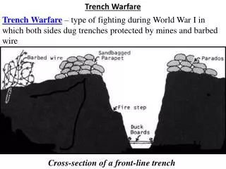
Failure to clear oxide Nitride erosion Oxide dishing Key Failures Caused by Imperfect CMP CMP is Not Perfect • Planarization window: Time window to stop CMP • Stopping sooner leaves oxide over nitride • Stopping later polishes silicon under nitride • Larger planarization window desirable • Step height: Oxide thickness variation after CMP • Quantifies oxide dishing • Smaller step height desirable • CMP quality depends on nitride and oxide density Control nitride and oxide density to enlarge planarization window and to decrease step height
Diffusion/Nitride Top view of layout Area available for fill insertion Top View Nitride α α Oxide Shrinkage = α Fill Insertion • CMP is pattern dependent Fill insertion improves planarization window and step height • Deposition bias: Oxide over nitride deposited with slanted profile Oxide features are “shrunk” nitride features • Size and shape fill to control nitride and oxide density
Outline • Introduction and Background • Problem formulations • Hexagon covering-based fill insertion • Experiments and results • Conclusions
Objectives for Fill Insertion • Primary goals: • Enlarge planarization window • Minimize step height i.e., post-CMP oxide height variation • Minimize oxide density variation Oxide uniformly removed from all regions Enlarges planarization window as oxide clears simultaneously • Maximize nitride density Enlarges planarization window as nitride polishes slowly Objective 1: Minimize oxide density variation Objective 2: Maximize nitride density
Dual-Objective Problem Formulation • Dummy fill formulation • Given: • STI regions where fill can be inserted • Shrinkage α • Constraint: • No DRC violations (such as min. spacing, min .width, min. area, etc.) • Objectives: • minimize oxide density variation • maximize nitride density
Density Variation Minimization with LP • Minimize oxide density variation • Use previously proposed LP-based solution • Layout area divided into n x n tiles • Density computed over sliding windows (= w x w tiles) • Inputs: • min. oxide density (|OxideMin|) per tile To compute: shrink design’s nitride features by α • max. oxide density (|OxideMax|) per tile To compute: insert max. fill, shrink nitride features by α • Output: target oxide density (|OxideTarget|) per tile • Dual-objective single-objective (nitride density) problem with oxide density constrained to |OxideTarget |
Nitride Maximization Problem Formulation • Dummy fill formulation • Given: • STI regions where fill can be inserted • Shrinkage α • Constraint: • No DRC violations (such as min. spacing, min .width, min. area, etc.) • Target oxide density (|OxideTarget|) • Objectives: • maximize nitride density
Outline • Introduction and Background • Problem formulations • Hexagon covering-based fill insertion • Experiments and results • Conclusions
Layout OD-OD Spacing Min. OD Width Feature Nitride STI Well Diffusion expanded by min. spacing Max. nitride fill Width too small Case Analysis Based Solution • Given |OxideTarget |, insert fill for max. nitride density • Solution (for each tile) based on case analysis • Case 1: |OxideTarget | = |OxideMax| • Case 2: |OxideTarget | = |OxideMin| • Case 3: |OxideMin| < |OxideTarget | < |OxideMax| • Case 1 Insert max. nitride fill • Fill nitride everywhere where it can be added • Min. OD-OD (diffusion-diffusion) spacing ≈ 0.15µ • Min. OD width ≈ 0.15µ • Other OD DRCs: min. area, max. width, max. area } More common due to nature of LP
α Hole Nitride α Top View β No oxide in this region Case 2: |OxideTarget | = |OxideMin| • Need to insert fill that does not increase oxide density • Naïve approach: insert fill rectangles of shorter side < α • Better approach: perform max. nitride fill then dig square holes of min. allowable side β Gives higher nitride:oxide density ratio • No oxide density in rounded square around a hole • Cover nitride with rounded squares no oxide density • Covering with rounded squares difficult approximate rounded squares with inscribed hexagons • Cover rectilinear max. nitride with min. number of hexagons
Covering Bulk Fill with Hexagons HU-Lines HU-Lines V-Lines HL-Lines HL-Lines V-Lines Key observation: At least one V-Line and one of HU- or HL- Lines of the honeycomb must overlap with corresponding from polygon Proof: In paper. (Can displace honeycomb to align one V-Line and one of HU- or HL-Line without needing additional hexagons.) Approach: Select combinations of V- and HL- or HU- Lines from polygon, overlap with honeycomb and count hexagons. Select combination with min. hexagons. Also flip polygon by 90º and repeat. Complexity: |Polygon V-Lines| x (|Polygon HL-Lines| + |Polygon HU-Lines|) x |Polygon area| Cover max. nitride fill with hexagons, create holes in hexagon centers
Oxide Area Outloss = Nitride Area Case 3: |OxideMin| < |OxideTarget | < |OxideMax| • Holes give high nitride:oxide density insert max. nitride fill and create holes to reduce oxide density • OK for nitride fill to contribute to oxide density approximate rounded squares by circumscribed hexagons • When max. nitride is covered with circumscribed hexagons, oxide density increases • If oxide density (=outloss x max. nitride area) < |OxideTarget| increase oxide density by filling some holes • If oxide density > |OxideTarget| decrease oxide density by partially using Case 2 solution
Solution Summary • Divide layout into tiles • Calculate |OxideMin| and |OxideMax| • Run LP-based fill synthesis for oxide variation minimization Get |OxideTarget | • If |OxideTarget | = |OxideMax| (i.e., max. oxide needed) Add max. nitride fill • If |OxideTarget | = |OxideMin| (i.e., add no more oxide) Add max. nitride fill Calculate inscribed hexagon size based on α and β Cover max. nitride fill with hexagons Create square holes in the center of hexagons • If |OxideMin| < |OxideTarget | < |OxideMax| (i.e., general case) Add max. nitride fill Calculate circumscribed hexagon size based on α and β Cover max. nitride fill with hexagons Create square holes in the centers of hexagons If oxide density lower than needed fill some holes If oxide density higher than needed Use inscribed hexagons in some region
Outline • Introduction and Background • Problem formulations • Hexagon covering-based fill insertion • Experiments and results • Conclusions
Experimental Setup • Two types of studies • Density analysis • Post-CMP topography assessment using CMP simulator • Comparisons between: • Unfilled • Tile-base fill (DRC-correct fill squares inserted) • Proposed fill • Our testcases: 2 large designs created by assembling smaller ones • “Mixed”: RISC + JPEG + AES + DES 2mm x 2mm, 756K cells • “OpenRisc8”: 8-core RISC + SRAM 2.8mm x 3mm, 423K cells + SRAM
Design features Inserted fill Tiling-based fill Fill with proposed approach Layout After Fill Insertion + Higher nitride density + Smaller variation in STI well size less variation in STI stress
Density Enhancement Results Testcase: Mixed Testcase: OpenRisc8 Tiled 0.5µ/0.5µ Tiled 1.0µ/0.5µ Tiled 1.0µ/1.0µ Unfilled Proposed + Significantly higher nitride density + Lower oxide density variation
Testcase Fill Approach Final Max. Step Height (nm) Planarization Window (s) Mixed Unfilled 142 45.3 Tiled 0.5µ/0.5µ 143 46.5 Proposed 129 53.6 OpenRisc8 Unfilled 146 42.7 Tiled 0.5µ/0.5µ 144 44.7 Proposed 133 50.4 Post-CMP Topography Assessment + Smaller step height less oxide height variation + Larger planarization window
Outline • Introduction and Background • Problem formulations • Hexagon covering-based fill insertion • Experiments and results • Conclusions
Conclusions • Imperfect STI CMP causes functional and parametric yield loss • Our fill insertion approach focuses on: (1) oxide density variation minimization, and (2) nitride density maximization • Large nitride fill features contribute to nitride and oxide densities, small ones to nitride only shape fill to control both densities • Proposed max. nitride fill insertion with holes to control oxide density and achieve high nitride density • Results indicate significant decrease in oxide density variation and increase in nitride density over tile-based fill • CMP simulation shows superior CMP characteristics, planarization window increases by 17%, and step height decreases by 9%
Acknowledgements • Prof. Duane Boning and Mr. Xiaolin Xie at MIT for help with abstractions of physical CMP phenomenon and STI-CMP simulator Thank You • Questions?