Download
1 / 33
330 likes | 592 Views
Computer Organisatie 2009 - Andy D. Pimentel. Pipeline Control and Hazards. Recap last lecture. All recent processors use pipelining Pipelining doesn’t help latency of single task, it helps throughput of entire workload Multiple tasks operating simultaneously using different resources

E N D
Computer Organisatie 2009 - Andy D. Pimentel Pipeline Control and Hazards
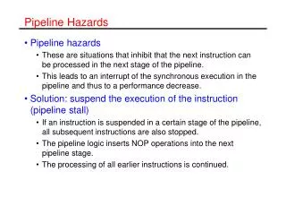
Recap last lecture • All recent processors use pipelining • Pipelining doesn’t help latency of single task, it helps throughput of entire workload • Multiple tasks operating simultaneously using different resources • Potential speedup = Number of pipe stages • Pipeline rate limited by slowest pipeline stage • Unbalanced lengths of pipe stages reduces speedup • Time to “fill” pipeline and time to “drain” it reduces speedup • Must detect and resolve hazards • Stalling negatively affects throughput • Today: pipeline control, including hazards
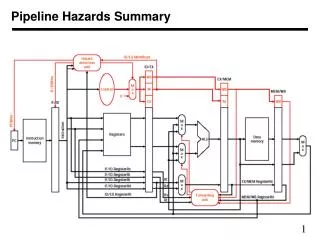
Pipeline Data and Control Paths 1 PCSrc ID/EX 0 EX/MEM Control IF/ID Add MEM/WB Branch Add 4 RegWrite Shift left 2 Read Addr 1 Instruction Memory Data Memory Register File Read Data 1 Read Addr 2 MemtoReg Read Address ALUSrc PC Read Data Address 1 Write Addr ALU Read Data 2 0 Write Data 0 Write Data 1 ALU cntrl MemWrite MemRead Sign Extend 16 32 ALUOp 0 1 RegDst
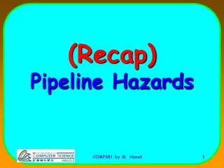
DM DM DM DM DM Reg Reg Reg Reg Reg Reg Reg Reg Reg Reg IM IM IM IM IM ALU ALU ALU ALU ALU A Way to “Fix” a Data Hazard Can fix data hazard by forwarding results as soon as they are available to where they are needed. add r1,r2,r3 I n s t r. O r d e r sub r4,r1,r5 and r6,r7,r1 or r8,r1,r1 sw r4,100(r1)
Data Forwarding (aka Bypassing) • Any data dependence line that goes backwards in time • EX stage generating R-type ALU results or effective address calculation • MEM stage generating lw results • Forward by taking the inputs to the ALU from any pipeline register rather than just ID/EX by • adding multiplexers to the inputs of the ALU so Rd can be passed back to either (or both) of the EX’s stage Rs and Rt ALU inputs • 00: normal input (ID/EX pipeline registers) • 10: forward from previous instr (EX/MEM pipeline registers) • 01: forward from instr 2 back (MEM/WB pipeline registers) • adding the proper control hardware • With forwarding, pipeline can run at full speed even in the presence of data dependencies
Data Forwarding Control Conditions • EX/MEM hazard: if (EX/MEM.RegWrite and (EX/MEM.RegisterRd != 0) and (EX/MEM.RegisterRd == ID/EX.RegisterRs)) ForwardA = 10 if (EX/MEM.RegWrite and (EX/MEM.RegisterRd != 0) and (EX/MEM.RegisterRd == ID/EX.RegisterRt)) ForwardB = 10 • MEM/WB hazard: if (MEM/WB.RegWrite and (MEM/WB.RegisterRd != 0) and (MEM/WB.RegisterRd == ID/EX.RegisterRs)) ForwardA = 01 if (MEM/WB.RegWrite and (MEM/WB.RegisterRd != 0) and (MEM/WB.RegisterRd == ID/EX.RegisterRt)) ForwardB = 01 Forwards the result from the previous instr. to either input of the ALU provided it writes and != R0. What’s wrong with this hazard control? Forwards the result from the second previous instr. to either input of the ALU provided it writes and != R0.
DM DM DM Reg Reg Reg Reg Reg Reg IM IM IM ALU ALU ALU A Complication • Another potential data hazard can occur when there is a conflict between the result of the WB stage instruction and the MEM stage instruction – which should be forwarded? More recent result! I n s t r. O r d e r add $1,$1,$2 add $1,$1,$3 add $1,$1,$4
Corrected Forwarding Control Conditions • MEM/WB hazard: if (MEM/WB.RegWrite and (MEM/WB.RegisterRd != 0) and (MEM/WB.RegisterRd == ID/EX.RegisterRs) and (EX/MEM.RegisterRd != ID/EX.RegisterRs || ~ EX/MEM.RegWrite)) ForwardA = 01 if (MEM/WB.RegWrite and (MEM/WB.RegisterRd != 0) and (MEM/WB.RegisterRd == ID/EX.RegisterRt) and (EX/MEM.RegisterRd != ID/EX.RegisterRt || ~ EX/MEM.RegWrite))) ForwardB = 01 Forward if this instruction writes AND its not writing R0 AND this dest reg == source AND in between instr. either doesn’t match dest. reg. OR it doesn’t write reg.
1 ID/EX 0 EX/MEM Control IF/ID Add MEM/WB Branch Add 4 Shift left 2 Read Addr 1 Instruction Memory Data Memory Register File Read Data 1 Read Addr 2 Read Address PC Read Data Address 1 Write Addr ALU Read Data 2 1 Write Data 0 Write Data 0 ALU cntrl 16 32 Sign Extend 0 EX/MEM.RegisterRd 1 IF/ID.RegisterRs Forward Unit MEM/WB.RegisterRd IF/ID.RegisterRt Datapath with Forwarding Hardware PCSrc
DM DM DM DM DM Reg Reg Reg Reg Reg Reg Reg Reg Reg Reg flush IM IM IM IM IM IM ALU ALU ALU ALU ALU ALU and r6,r1,r7 and r6,r1,r7 or r8, r1, r9 or r8, r1, r9 xor r4,r1,r5 xor r4,r1,r5 DM Reg Forwarding with Load-use Data Hazards lw r1,100(r2) I n s t r. O r d e r sub r4,r1,r5 sub r4,r1,r5
Load-use Hazard Detection Unit • Need a hazard detection unit in the ID stage that inserts a stall between the load and its use • ID Hazard Detection if (ID/EX.MemRead and ((ID/EX.RegisterRt = IF/ID.RegisterRs) or (ID/EX.RegisterRt = IF/ID.RegisterRt))) stall the pipeline • The first line tests to see if the instruction is a load; the next two lines check to see if the destination register of the load in the EX stage matches either source registers of the instruction in the ID stage • After this 1-cycle stall, the forwarding logic can handle the remaining data hazards
Stall Hardware • In addition to the hazard detection unit, we have to implement the stall • Prevent the IF and ID stage instructions from making progress down the pipeline, done by preventing the PC register and the IF/ID pipeline register from changing • Hazard detection unit controls the writing of the PC and IF/ID registers • The instructions in the back half of the pipeline starting with the EX stage must be flushed (execute noop) • Must deassert the control signals (setting them to 0) in the EX, MEM, and WB control fields of the ID/EX pipeline register. • Hazard detection unit controls the multiplexer that chooses between the real control values and 0’s. • Assume that 0’s are benign values in datapath: nothing changes
PCSrc 1 ID/EX.MemRead ID/EX 0 EX/MEM IF/ID Control 0 Add MEM/WB Branch Add 4 Shift left 2 Read Addr 1 Instruction Memory Data Memory Register File Read Data 1 Read Addr 2 Read Address PC Read Data Address 1 Write Addr ALU Read Data 2 1 Write Data 0 Write Data 0 ALU cntrl 16 32 Sign Extend 0 1 Forward Unit ID/EX.RegisterRt Adding the Hazard Hardware Hazard Unit 0 1
DM DM Reg Reg Reg Reg IM IM ALU ALU Memory-to-Memory Copies • For loads immediately followed by stores (memory-to-memory copies) can avoid a stall by adding forwarding hardware from the MEM/WB register to the data memory input. • Would need to add a Forward Unit to the memory access stage • Should avoid stalling on such a load I n s t r. O r d e r lw $1,10($2) sw $1,10($3)
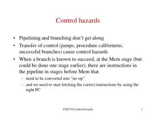
Control Hazards • When the flow of instruction addresses is not what the pipeline expects; incurred by change of flow instructions • Conditional branches (beq, bne) • Unconditional branches (j) • Possible solutions • Stall • Move decision point earlier in the pipeline • Predict • Delay decision (requires compiler support) • Control hazards occur less frequently than data hazards; there is nothing as effective against control hazards as forwarding is for data hazards
Jump 1 PCSrc 1 0 ID/EX Shift left 2 EX/MEM 0 IF/ID Control Add MEM/WB PC+4[31-28] Branch Add 4 Shift left 2 Read Addr 1 Instruction Memory Data Memory Register File Read Data 1 Read Addr 2 Read Address PC Read Data Address 1 Write Addr ALU Read Data 2 1 Write Data 0 Write Data 0 ALU cntrl 16 32 Sign Extend 0 1 Forward Unit Datapath Branch and Jump Hardware
DM DM DM Reg Reg Reg Reg Reg Reg IM IM IM ALU ALU ALU stall Jumps Incur One Stall • Jumps not decoded until ID, so one stall is needed • Fortunately, jumps are very infrequent – only 2% of the SPECint instruction mix j I n s t r. O r d e r lw and
DM DM Reg Reg Reg Reg IM IM IM ALU ALU ALU stall stall stall lw DM Reg and Recap: Branches Incur Three Stalls Can fix branch hazard by waiting – stall – but affects throughput beq I n s t r. O r d e r
Moving Branch Decisions Earlier in Pipe • Move the branch decision hardware back to the EX stage • Reduces the number of stall cycles to two • Adds an and gate and a 2x1 mux to the EX timing path • Add hardware to compute the branch target address and evaluate the branch decision to the ID stage • Reduces the number of stall cycles to one (like with jumps) • Computing branch target address can be done in parallel with RegFile read (done for all instructions – only used when needed) • Comparing the registers can’t be done until after RegFile read • comparing and updating the PC adds a comparator, an and gate, and a 3x1 mux to the ID timing path • Need forwarding hardware in ID stage • For longer pipelines, decision points are later in the pipeline, incurring more stalls, so we need a better solution
Early Branch Forwarding Issues • Bypass of source operands from the EX/MEM if (IDcontrol.Branch and (EX/MEM.RegisterRd != 0) and (EX/MEM.RegisterRd = IF/ID.RegisterRs)) ForwardC = 1 if (IDcontrol.Branch and (EX/MEM.RegisterRd != 0) and (EX/MEM.RegisterRd = IF/ID.RegisterRt)) ForwardD = 1 Forwards the result from the second previous instr. to either input of the Compare • MEM/WB “forwarding” is taken care of by the normal RegFile write before read operation • If the instruction immediately before the branch produces one of the branch compare source operands, then a stall will be required since the EX stage ALU operation is occurring at the same time as the ID stage branch compare operation
IF.Flush 0 0 1 Supporting ID Stage Branches PCSrc Branch 1 Hazard Unit ID/EX 0 EX/MEM 0 1 0 Control IF/ID Add MEM/WB 4 Shift left 2 Add Compare Read Addr 1 Instruction Memory Data Memory RegFile Read Addr 2 Read Address Read Data 1 PC Read Data 1 Write Addr ALU Address 1 ReadData 2 Write Data 0 Write Data 0 ALU cntrl 16 Sign Extend 32 Forward Unit Forward Unit
Branch Prediction • Resolve branch hazards by assuming a given outcome and proceeding without waiting to see the actual branch outcome • Predict not taken – always predict branches will not be taken, continue to fetch from the sequential instruction stream, only when branch is taken does the pipeline stall • If taken, flush instructions in the pipeline after the branch • in IF, ID, and EX if branch logic in MEM – three stalls • in IF if branch logic in ID – one stall • ensure that those flushed instructions haven’t changed machine state – automatic in the MIPS pipeline since machine state changing operations are at the tail end of the pipeline (MemWrite or RegWrite) • restart the pipeline at the branch destination
I n s t r. O r d e r DM DM DM DM Reg Reg Reg Reg Reg Reg Reg Reg flush IM IM IM IM ALU ALU ALU ALU 16 and $6,$1,$7 20 or r8,$1,$9 Flushing with Misprediction (Not Taken) • To flush the IF stage instruction, add a IF.Flush control line that zeros the instruction field of the IF/ID pipeline register (transforming it into a no-op) 4 beq $1,$2,2 8 sub $4,$1,$5
Branch Prediction (cont’d) • Resolve branch hazards by statically assuming a given outcome and proceeding • Predict taken – always predict branches as taken • Predict taken always incurs a stall (if branch destination hardware has been moved to the ID stage) • As the branch penalty increases (for deeper pipelines), a simple static prediction scheme will hurt performance • With more hardware, possible to try to predict branch behavior dynamically during program execution • Dynamic branch prediction – predict branches at run-time using run-time information
Dynamic Branch Prediction • A branch prediction buffer (aka branch history table (BHT)) in the IF stage, addressed by the lower bits of the PC, contains a bit that tells whether the branch was taken the last time it was executed • Bit may predict incorrectly (may be from a different branch with the same low order PC bits, or may be a wrong prediction for this branch) but it doesn’t affect correctness, just performance • If the prediction is wrong, flush the incorrect instructions in pipeline, restart the pipeline with the right instructions, and invert the prediction bit • The BHT predicts when a branch is taken, but does not tell where its taken to! • A branch target buffer (BTB) in the IF stage can cache the branch target address (or !even! the branch target instruction) so that a stall can be avoided
2-bit Predictors • A 2-bit scheme can give 90% accuracy since a prediction must be wrong twice before the prediction bit is changed right 9 times Loop: 1st loop instr 2nd loop instr . . . last loop instr bne $1,$2,Loop fall out instr wrong on loop fall out Taken Not taken 1 Predict Taken Predict Taken 1 Taken right on 1st iteration Not taken Taken Not taken 0 Predict Not Taken Predict Not Taken 0 Taken Not taken
Instruction level parallelism • Go beyond single instruction pipeline, achieve IPC > 1 • Dispatch multiple instructions per cycle • Geared for sequential code that is hard to parallelize otherwise • Exploit fine-grained or instruction-level parallelism (ILP)
Classifying ILP Machines • Superpipelined: cycle time = 1/m of baseline • Issue parallelism = IP = 1 inst / minor cycle • Operation latency = OP = m minor cycles • Peak IPC = m instr / major cycle (m x speedup?)
Classifying ILP Machines • Superscalar: • Issue parallelism = IP = n inst / cycle • Operation latency = OP = 1 cycle • Peak IPC = n instr / cycle (n x speedup?)
Execution of VLIW Instructions Classifying ILP Machines • VLIW: Very Long Instruction Word • Issue parallelism = IP = n inst / cycle • Operation latency = OP = 1 cycle • Peak IPC = n instr / cycle = 1 VLIW / cycle
Out-of-Order (OoO) execution • Nowadays, most general-purpose processors are superscalar with out-of-order execution • Instructions are dynamically scheduled to one of the parallel pipelines • Instructions • enter the processor in-order • are executed out-of-order • write-back their results in-order again • Requires substantial hardware support, e.g. • OoO control : find dependencies and adhere to them • Using solutions from the 1960’s! • Additional physical registers • Pentium 4 has only 8 “architectural registers” but 128 physical registers