Download
1 / 43
430 likes | 619 Views
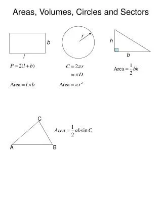
An automated calibration system for telematic music applications. Jonas Braasch Communication Acoustics and Aural Architecture Research Laboratory (C A 3 R L) Rensselaer Polytechnic Institute, Troy, NY http://symphony.arch.rpi.edu/~carl. Steinberg and Snow (1934). Location A. Location B.

E N D
An automated calibration system for telematic music applications Jonas Braasch Communication Acoustics and Aural Architecture Research Laboratory (CA3RL) Rensselaer Polytechnic Institute, Troy, NY http://symphony.arch.rpi.edu/~carl
Steinberg and Snow (1934) Location A Location B
Biggest Challenges • Bandwidth • Transmission latency • Feedbacks • Communication during setup. …you will need to make friends with the sysadmin
Necessary Bandwidth • Telematic Circle • The transmission of DV quality video requires a bandwidth of 25 Megabits/s • 8 channels of CD quality audio about 5.5 Megabits/s. • McGill University (Jeremy Cooperstock) • Gigabit/s AV connection for HD uncompressed • Fraunhofer-Erlangen • New Fraunhofer/Erlangen low-latency coder AAC-LD (about 5 ms for the coding/decoding process), will be integrated into CISCOs’ system.
Transmission Delay • Acceptable latency for music: 25 milliseconds. • Speed of light • Signal traveling between RPI in Troy, NY and CCRMA at Stanford University, Palo Aalto, CA: 14 ms for the distance of 4,111 km (direct line). • 54 ms for a connection between New York and Australia (16,000 km) • Speed of sound • 14 ms=6 m (c=430 m/s at room temperature) • Total delay • transmission delay (determined by physical distance propagation speed of the signal) • signal-processing delay
Feedback loop in telematic connections Longer transmission delays are easier to detect audibly!
Echo feedback • Audible colorations and echoes are a common side effect in two-way transmission systems. • Audio/videoconferencing systems such as iChat or Skype use echo-cancellation systems to suppress feedbacks. • In speech communication echo-cancellation systems work well, since the back-and-forth nature of spoken dialogue usually allows to temporarily suppress the transmission channel in one direction. • In simultaneous music communication, however, this procedure tends to cut-off part of the performance. • Solution: capture music signals with closely spaced microphones (e.g., lavalier microphones).
Telematic Circle Members • Deep Listening Institute • Pauline Oliveros, Sarah Weaver • Rensselaer Polytechnic Institute • Curtis Bahn, Jonas Braasch, Pauline Oliveros • Stanford University (CCRMA) • Chris Chafe, Ge Wang • University of California San Diego • Mark Dresser, Shahrokh Yadegari, Adriene Jenik, Victoria Petrovich • McGill University • Jeremy Cooperstock, Bill Martens
Telematic Circle Concerts • March 22: RPI, Northwestern, Stanford • June, 26: ICAD 2007, Montreal • McGill, Korea, RPI, Stanford • Aug 6-7, SIGGRAPH 2007, San Diego • UCSD, RPI, Stanford/Banff • Nov 16, 2007: Stanford, RPI, UCSD • Dec 14, ISIM 2007: RPI, Northwestern • Aug 28, ICMC 2008, RPI, Belfast, Stanford
Problem • Automatic tracking of actors required during a theater film shoot • Typically, the actors are recorded closely with lavalier microphones + good dry sound quality Spatial aspects of the recordings are lost and need to be recovered
Possible Solutions to track actors • Optical tracking: works well but can fail in bright stage light • GPS: only works outdoors • Electromagnetic tracking (e.g., via sender for lavalier mic): works only outdoors (reflections occur indoors) • Acoustic tracking: works well for single sound sources, problematic in multiple sound source scenarios
Acoustic Tracking Solutions • Beamforming • Methods based on interchannel delay • Both methods work only well for single sound sources • Need to find time-frequency windows in which only one sound source is present. • Lavalier microphone data can be used for this purpose.
Sketch of the recording and reproduction set-up ViMiC=Virtual Microphone Control (Multichannel sound spatialization software)
Microphone Array • Microphone array was positioned in the center of the room, 186 cm above the ground. • consists of 5 omni-directional microphones (Earthworks M30). • square-based pyramid dimensions: base side: 14 cm, triangular side 14 cm.
Estimation of the signal-to-noise ratios for each sound source
Test material • Material recorded during a theatre production. • Room acoustics was typical for a small theatre and not reverberation free. • Four actors were equipped with lavalier microphones.
Analyses methods • programmed in MATLAB • A filter bank of five octave-band wide IIR filters (Chebyshev Type-I filters, 125 Hz to 2 kHz center frequencies. • A running time-window was applied (Hanning, 100-ms filter length). For each time/frequency bin, the signal-to-noise ratio was determined according to Eq. 1. • Sound source estimation (if SNR > 4 dB) • cross-correlation technique • information theoretic delay criterion (ITDC) algorithm [Mod:88]
DOA for the left/right angle with the speed of sound c, the sampling frequency fs, the internal delay , and the distance between both microphones d DOA=Direction of Arrival
Conclusions • Initial results promising. • Significant improvement was observed when the cross correlation method was replaced with the information theoretic delay criterion algorithm. • A real-time application will be implemented in future
Literature • [Fri:80] Fritsch, F. N. and R. E. Carlson, Monotone Piecewise Cubic Interpolation, SIAM J. Numerical Analysis, Vol. 17, 1980, pp.238–246 • [Jot:92] Jot, J.-M. (1992) Étude et réalisation d'un spatialisateur de sons par modèls physiques et perceptifs, Doctoral dissertation, Télécom Paris. • [Mod:88] R. Moddemeijer, An information theoretical delay estimator, Ninth Symp. on Information Theory in the Benelux, May 26–27, 1988, Mierlo (NL), pp. 121–128, Ed. K.A. Schouwhamer Immink, Werkgemeenschap Informatie- en Communicatietheorie , Enschede (NL). • [Pul:97] Pulkki, V. (1997) Virtual sound source positioning using vector base amplitude panning}, J. Audio Eng. Soc. 45, 456–466. • [Wür:97] W. Würfel (1997) Passive akustische Lokalisation [passive acoustical localization], Master's Thesis, Technical University Graz.
Outlook • Expand telematic Circle (contact: braasj@rpi.edu) • Integration of haptics into the transmission system • Get Acoustic Tracking system to work in real-time
AV integration Valente & Braasch, Acustica 2008
virtual sound source virtual microphones floor
Blumlein XY-Technique Signal left channel Signal right channel Angle of arrival Directivity pattern right microphone Directivity pattern left microphone
Blumlein XY-Technique Signal left channel Signal right channel –45° Angle of arrival Directivity pattern right microphone Directivity pattern left microphone
Blumlein XY-Technique Signal left channel Signal right channel –45° +45° Angle of arrival Directivity pattern right microphone Directivity pattern left microphone
Blumlein XY-Technique Signal left channel Signal right channel –45° 0° +45° Angle of arrival Directivity pattern right microphone Directivity pattern left microphone
Stereophony >> l=-30° r=30° a a