Download

1 / 22
220 likes | 607 Views
POWER TRANSMISSION Motion convertion . ROTARY TO LINEAR motion convertion is concerned with taking the rotational motion and torque from an actguator and producing a linear motion and force on the output Lead screw Rack and pinion Slider cranks Cams. Lead screws .

E N D
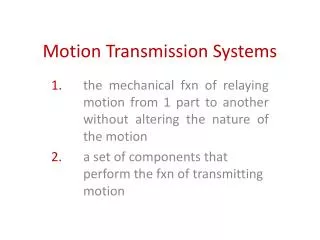
ROTARY TO LINEAR • motion convertion is concerned with taking the rotational motion and torque from an actguator and producing a linear motion and force on the output • Lead screw • Rack and pinion • Slider cranks • Cams
Screw is fixed with its ends free to rotate: as the screw is turned, the nut moves along the shaft with the payload attached A rotary displacement of the input shaft θ1 causes a linear motion of the payload x X=θ·P (P pitch of the screw mm/rev) This equation may be differentiated any number of times in order to obtain the relationship among linear velocity, acceleration and jerk and rotational relative quantities How a load on th output is seen by the input? i.e. Equivalent torque-inertia system For linear motion of the payload mass the kinetic energy is:Ek = ½ MVL² The corresponding kinetic energy of a torque-inertia systemEk = ½ Jeqω² Solving for the inertia, after relating rotary and linear velocity with the pitch Jeq = M·(P/2π)² reflected inertia reduced by smaller pitch
The pinion is the small gear attached to the actuator and the rack is a linear member with gear teeth on one side. The transfer relationship of such a mechanism is X = 2πrθ The linear distance traveled is proportional to the input shaft rotations (in revs) with the constant of porportionality equal to the circumference of the pinion that is the linear distance traveled is equal to the distance traveled by the pinion The reflected inertia, as seen by the input shaft, is Jeq = Mr²
The slider-crank mechanism is an extremely cost-effective means of converting rotary to linear motion. The crank portion is the wheel that rotates about its center and has a rod of fixed lenght mounted to a point on its circumference; the other end of the connecting rod is attached to a linear stage which is constrained to move in only one dimension on a relatively frictionless surface. At both its location the connecting rod is free to rotate thus the angle formed with the horizontal will change as a function of the disk’s position. As the disk travels from 0 to 180° in the counterclockwise direction, the linear stage moves a distance equal to 2r: if the disk continues to travle from 180° back to 0° - still in counterclockwise direction, the load will move in the opposite direction over exactly the same linear distance.
Full extension and retration of the linear stage are called DEAD POINTS FLYWHEEL with sufficient inertia must be connected to the crank’s axis of rotation because when connectin rod and crank are in line at a dead point, the direction of rotation may go either way If the input shaft is rotated continuously at some velocity, the motion of the linear stage is reciprocating. Torque seen by the input and relationship between the input shaft’s position are nonlinear in nature
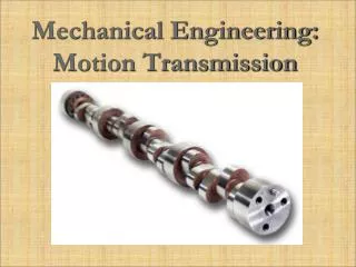
Cams Cams can be considered as mechanisms with memory since they contain in their design information about the output law of motion. Many application requirements have lead to different kind of cams. Let’s see…
Cams – design criteria Law of motion for the follower: position, velocity, acceleration and jerk Machining problems: undercut Pressure angle