Slide Note
0 likes | 10 Views
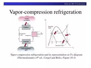
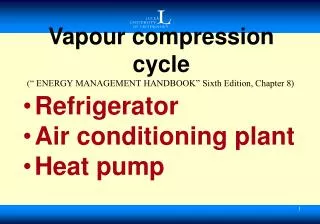
The performance of a vapor compression cycle is influenced by various operating conditions like superheating the suction vapor, subcooling the liquid, evaporator pressure, and condenser pressure. Superheating reduces COP but increases discharged temperature and rejected heat. Subcooling enhances cycle performance by reducing liquid flashing during expansion. Changes in evaporator and condenser pressure affect refrigerating capacity and power consumption. The addition of a liquid-vapor heat exchanger can further impact COP and HP/TR values of the system.

E N D
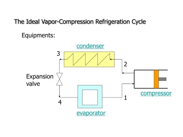
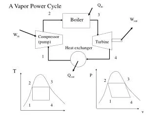
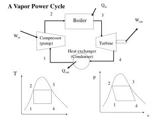
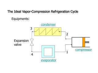
Actual vapor compression Actual vapor compression cycle cycle Prof.Dr.M.M.Nasr Professor of refrigeration and air conditioning Minia university
1 1- - Effect of operating Effect of operating conditions on the conditions on the performance of the vapor performance of the vapor compression cycle compression cycle 1.Effect of superheating the suction vapor a.Heating in the evaporator: The refrigerant vapor in the evaporator will be absorbing heat continuously and will continue to absorb heat even after the evaporator. b.Heating between the evaporator and compressor c.Heating in the cylinder head Superheating occurs outside the evaporator: the refrigerating effect per unit mass of refrigerant circulated is same. Moreover, the COP of the superheated cycle reduces in comparison to the saturated cycle. compression per kilogram w1a-2b > w1-2 discharge temperature T2b > T2 rejected heat per kilogram q2b-3> qb-3 compressor compress a greater volume v1a > v1
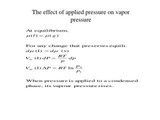
2.Effect of subcooling the liquid Subcooling means cooling the liquid refrigerant from state 3 to 3a as shown in Figure. From the figure, it is clear that subcooling of the liquid increases the refrigerating effect and also reduces the flashing of the liquid during the expansion process. Therefore, the performance of the cycle improves which means that the compressor power and its displacement will be smaller per ton of refrigeration
3.Effect of evaporator 3.Effect of evaporator pressure pressure Evaporator is a loop of tube coil through which the refrigerant flows in a mixed condition. While flowing, its pressure from evaporator inlet to its outlet decreases due to friction. The value of drop in pressure depends on the type of flow, evaporator tube diameter, length, number of bends, etc. In all, there is some pressure drop in the evaporator.
4.Effect of condenser 4.Effect of condenser pressure pressure An increase in condenser pressure results in a decrease in refrigerating capacity and an increase in power consumption. This is represented by a p-h diagram using saturated cycle, in Figure. The decrease in refrigerating capacity is due to a decrease in the refrigerating effect and volumetric efficiency. The increase in power consumption is due to increased mass flow (due to decreased refrigerating effect) and an increase in specific work (due to increased pressure ratio), although the isentropic line remains unchanged.
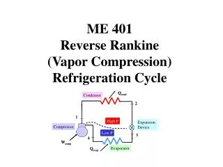
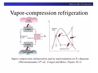
Vapor Compression System with Liquid Vapor Compression System with Liquid- -Vapor Regenerative Heat Exchanger Regenerative Heat Exchanger • Example ( ) (a) A Freon 12 simple saturation cycle operates at temperatures of 35 °C and -15°C for the condenser and evaporator respectively. Determine the COP • and HP/TR of the system. • (b) If a liquid-vapour heat exchanger is installed in the system, with the temperature of the vapor leaving the heat exchanger at 15°C, what will be the change in the COP and HP/TR? • Solution Vapor
(a) Simple saturation cycle (b) Liquid-vapor heat exchanger cycle Now, h1’– h1 = 199.45 - 181 = 18.45 = h3– h3', Hence, h3’ = 69.5 - 18.45 = 51.05 kJ/kg qo = h1– h3 =181 - 69.5 = 111.5 kJ/kg q0’ = h1– h3’ = 181 - 51.05 = 129.95 kJ/kg w = h2– h1 = 208.2- 181 = 27.2 kJ/kg w = h2’– h1’ =230.4 - 199.45 = 30.95 kJ/kg COP = 111.5/ 27.2 = 4.09 COP= 129 95/30.5=4.199 kJ/kg HP/TR = =4.761/4.09=1.16 HP/TR = 4.761/4.199 = 1.134 Increase in COP = [(4.199 -4.09)/4.09] (100) = 2.56% Decrease in HP/TR =[(1.16 /1.134)/ 1.2] (100) = 2.5%
Note Theoretically, the increase in COP is not very large for Freon 12. And For Freon 22 there is, in fact a decrease in COP. However, superheat improves the performance by ensuring complete vaporization of liquid. In refrigerators and air conditioners, the capillary tube is joined to the suction line, thus forming a regenerative heat exchanger. If we define the effectiveness of the LSHX, εLSHX as the ratio of actual heat transfer rate in the LSHX to maximum possible heat transfer rate, then: ) ( ) ( 1 3 1 3 max T T T T cp m Q v r . r ( ) Q m cp T T T T ' 1 1 ' 1 1 act v HE . ( )
ACTUAL VAPOUR ACTUAL VAPOUR COMPRESSION CYCLE COMPRESSION CYCLE ld-lc ,Superheating of the vapor in the evaporator. lc-lb Heat gain and superheating of the vapor in the suction line. lb-la Pressure drop in the suction line,. la-1 Pressure drop due to wire drawing at the compressor-suction valve. 1-2 Polytropic compression with friction and heat transfer to the surroundings instead of isentropic compression. 2-2a Pressure drop at the compressor-discharge valve. 2a-2b.Pressure drop in the delivery line. 2b-2c Heat loss and desuperheating of the vapour in the delivery line. 2b-3Pressure drop in the condenser. 3-3a Subcooling of the liquid in the condenser or subcooler. 3a-3b Heat gain in the liquid line. The lines 3-3a and 3a-3b are along the saturated liquid line on the T-s diagram as the constant pressure lines in liquid region run close to it 4-Id Pressure drop in the evaporator.
The heat rejected in the polytropic compression process can be obtained by applying the SSSF energy equation q = (h2- h1) + w => - w = (h2- h1|) - q ( ) Equation ( ) represents the energy balance of the compressor, viz.. Work of compression = Increase in enthalpy of gas + Heat lost in cooling
Example Example • An ammonia compression machine is required to cater for a load of 100 tons. The cooling water temperature requires the condenser to work at 35°C and the brine temperature requires evaporator to work at -30°C. Temperature at entry to expansion valve 30°C. The vapour is superheated 5.5°C in evaporator and further superheats by 14°C in suction line. Pressure drop in suction and discharge valves is 0.02 bar and 0.03 bar respectively. The vapour heats up by 10°C by picking up heat from cylinder walls. Compression index n = 1.2. Discharge vapour cools down by 55°C in discharge line before entry to condenser. Compressor is 2-cylinder single acting running at 560 rpm and volumetric efficiency is 0.57. Ignore the losses e.g., pressure drop in condenser, evaporator and piping and heat transfer in liquid line etc. • Draw the cycle on a P-h diagram and determine: • (a) B.P. of the compressor if Mech. efficiency is 75% • (b) Bore and stroke of the cylinder if L/D = 1.25 • (c) Condenser water required for a temperature rise of 6°C.
Thanks Prof.Dr.M.M.Nasr Mechanical Power and Energy Dept.