Download
1 / 28
280 likes | 374 Views
Phase and Gain stability of optical fibre link used in MeerKAT. Author : Roufurd Julie Supervised by : Prof Michael Inggs SKA HCD bursary conference Dec 2008. Outline of Presentation. Background / Introduction to project Project Objective Relevance of Project to SKA/KAT

E N D
Phase and Gain stability of optical fibre link used in MeerKAT Author : Roufurd Julie Supervised by : Prof Michael Inggs SKA HCD bursary conference Dec 2008
Outline of Presentation • Background / Introduction to project • Project Objective • Relevance of Project to SKA/KAT • Methodology & Results • Conclusions
Background / introduction to project • The meerKAT project consists of 80 antennas configured as an interferometer • Optical fibre is used to transport the RF signal • Interferometry requires a GAIN and PHASE stable RF path
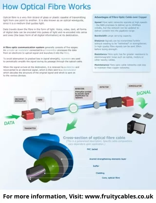
Why Optical fibre? Very high bandwidth -> greater sensitivity Low attenuation -> signal travel further
Why analogue optical modulation? Advantages • Simpler and cheaper • Geographically separate the noisy digital backend from sensitive RF front end Disadvantages • Needs much better S/N than digital • Limited dynamic range (at this stage!) • Signal travels further before being digitised, and is susceptible to amplitude and phase effects
Background / introduction to project • The meerKAT project consists of 50+ antennas configured as an interferometer • Optical fibre is used as the signal medium • Interferometry requires a GAIN and PHASE stable RF path
Defining PHASE and GAIN stability • Stability in this research, means some parameter change in terms of time • GAIN stability is GAIN change over time • Similarly PHASE stability is PHASE change over time. • Ideally, GAIN and PHASE should be constant with time (all other things being equal)
Relevance of project to KAT / SKA / other • Phase instability has a deleterious effect on the GAIN of the synthesised beam i.e. % decorrelation • Not good for Imaging dynamic range • GAIN stability has an influence on the sensitivity of the radio telescope • These effects need to quantified as it influences how often system needs to be calibrated
Project objectives • Investigate properties of the optical fibre path that affects phase and gain stability • Measure and report on performance of optical link using a commercial Tx and Rx pair.
Some quick facts • Ambient temperature around cable affects phase stability • Loose-tube cabled optical fibre has been shown to have the lower of the delay/kelvin coefficients • Bending of fibre causes attenuation which affects gain stability • Laser Tx power is affected by temperature, thus these units need to be kept at constant temperature • Units used were Miteq & Photonics, 1550nm, DFB laser with external modulation
Methodology • Find out phase requirements from the meerKAT Imaging team. (Not complete success yet) • Study physical properties of components in the Optical fibre chain that contribute to phase and amplitude instabilities • Create engineering tools to measure the stability • Quantify VNA and optical terminal equipment stabilities • Study the HartRAO optical fibre link installation
Results 4 – Phase @ 1.5GHz vs Azimuth position (mean removed)
Conclusions • This optical path will have an effect on the amplitude and phase performance of the system • I measured the performance of the HartRAO links. • Movement of the dish affects GAIN more, while Temperature affects PHASE more • Data analysis still in progress
Acknowledgements • SKA HCD for bursary funding • Mike Inggs and Venkat for their daily inputs • Mike Gaylard for his many hours of trying to explain interferometry to me • KAT project office for usage of measuring equipment • KAT and HartRAO staff for their various bits and pieces along the way.