Download
1 / 67
1.16k likes | 1.96k Views
Distributed Shared Memory (DSM). Distributed Shared Memory. Message Passing Paradigm Send (recipient, data) Receive (data) Shared Memory Paradigm Data= Read (address) Write (address, data). easy to implement hard to program no global clock

E N D
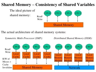
Distributed Shared Memory • Message Passing Paradigm Send (recipient, data) Receive (data) • Shared Memory Paradigm Data= Read (address) Write (address, data)
easy to implement • hard to program • no global clock • no common memory LOCAL MEMORY PROCESSOR LOCAL MEMORY PROCESSOR Message Passing
SHARED DATA • easy to program • hard to implement PROCESSOR PROCESSOR Distributed Shared Memory
Distributed Shared Memory • For loosely coupled distributed systems, no physically shared memory is available. • A software layer is implemented on top of the message passing communication system in loosely coupled distributed-memory system to provide a shared memory abstraction to the programmers. • It provides a virtual address space among processes on loosely coupled processors. • Implemented either in an operating system or in runtime library routines with proper kernel support.
Architecture of DSM Systems • DSM is an abstraction that integrates the local memory of different machines in a network environment into a single logical entity shared by all co-operating processes executing on multiple sites. • Also known as Distributed Shared Virtual memory (DSVM).
Each node of the system consists of one or more CPU and a memory unit. Main memory of each node is used to cache pieces of the shared memory space. • A software memory-mapping manager routine in each node maps the local memory on to a shared virtual memory. • When process node makes a request , memory mapping manager takes charge of it. If required data block is not present in local memory, network page fault is generated & control is passed to operating system. The missing block is migrated from remote node to client’s node & is mapped into application’s address space. • Data caching is used to reduce the network latency. • The basic unit of data transfer or caching is a memory block. • High degree of locality of data accesses reduces network traffic.
Advantages of DSM • Simpler abstraction • Shields programmers from low level concerns • Better portability of distributed application program • Distributed application programs written for shared memory processor can be executed on DSM system without any change. • Better performance of some application • Locality of data • Ongoing On-demand data movement rather than separate data-exchange phase • Larger memory space
Flexible communication environment • Co existence of sender & receiver not necessary • Does not require recipient information • Ease of process management • Migrant process can leave its address space on its old node at the time of migration & fetch required pages from its new node on demand at time of accessing.
Design and Implementation Issue of DSM • Granularity • Block size • Structure of shared memory space • Memory coherence and access synchronization • Consistency of a shared data lying in main memories of two or more nodes & dealing with concurrent accesses • Data location and access • Replacement strategy • Thrashing • Data block gets transferred back & forth at a high rate if two nodes compete for write access to it. • Heterogeneity
P1 P2 • False Sharing Granularity • Factors influencing block size selection • Paging overhead • Less for large block size because of locality of reference • Directory size • Larger block size, smaller directory • Thrashing • More in larger blocks, as data in same data block may be updated by multiple nodes at same time • False sharing • More in larger blocks, when two processes access two unrelated variables that reside in same data block
Use page size as block size • Allows the use of existing page-fault scheme. • Allows access right control to be integrated into memory management unit. • If page can fit into packet, it does not impose undue communication overhead. • Suitable data entity for memory contention.
Structure of Shared Memory Space • Structure defines the abstract view of the shared – memory space to be presented to the application programmers of a DSM system. • No structuring • Linear array of words • Can choose fixed grain size for all applications • DSM simple • Structuring by data type • Collection of objects or variables in source language • Granularity is object or variable • DSM complicated as grain size can be variable • Structuring as a database • Ordered as a associative memory called tuple space • Requires programmers to use special access functions to access shared memory space, thus, data access is non transparent.
Consistency Models • To improve performance, DSM systems rely on replicating shared data items and allowing concurrent access at many nodes. However, if the concurrent accesses are not carefully controlled, memory accesses may be executed in an order different from that which the programmer expected. • A consistency model basically refers to the degree of consistency that has to be maintained for the shared memory data. • It is defined as a set of rules that applications must obey to ensure consistency of memory. • Better concurrency can be maintained by relaxing consistency requirement.
Strict (Atomic) Consistency Model • Strongest form of memory coherence. • Any read to a memory location X returns the value stored by the most recent write operation to X (changes are instantaneous). • Implementation requires the existence of an absolute global time. • Possible only on uniprocessor.
Strict Consistency • Difficult to Implement as - • Network latency • Difficult to determine global time • No global synchronization Natural Strict Consistency
Sequential Consistency Model • Weaker than strict consistency model. • Every node of the system sees the operations on the same memory part in the same order, although the order may be different from the order of issuing the operations. • The exact order in which the memory access operation are interleaved does not matter. • If three operations r1, w1, r2 are performed on a memory address, any ordering (r1, w1, r2), (r2, w1, r1), (w1, r2 ,r1), (r2, r1, w1) is acceptable provided all processors see same ordering. • Implementation require to ensure that no memory operation is started until all the previous one have been completed. • Provides single copy semantics as all processes sharing a memory location always see exactly the same contents stored in it.
Causal Consistency Model • Writes that are potentially causally related must be seen by all processes in the same order. Concurrent (Operations that are not causally related) writes may be seen in a different order on different machines. • Suppose that process P1 writes a variable X. Then P2 reads X and writes Y. Reading of X and writing of Y are potentially causally related because the computation of Y may have depended on the value of X read by P2. • If a write operation w1 is casually related to w2 then ( w1, w2 ) is acceptable but not ( w2, w1 ) . • Implementation require to keep track of dependent memory reference using dependency graph.
Pipelined Random Access Memory (PRAM) Consistency Model • Also known as FIFO consistency. • Writes done by a single process are received by all other processes in the order in which they were issued, but writes from different processes may be seen in a different order by different processes. • Ex. Process P1 executes w11 & w12 Process P2 executes w21 & w22 P3 sees it as (w11 , w12)(w21 , w22) P4 sees it as (w21 , w22) (w11 , w12 ) • All write operations performed by single process are in pipeline. • Can be implemented by sequencing the write operation of each node independently.
Processor Consistency Model • PRAM consistent with additional restriction of memory coherence, i.e. for every memory location x, there be a global agreement about order of writes to x. • All write operations performed on the same memory location (no matter by which process they are performed) are seen by all processes in the same order. • Ex. Process P1 executes w11 & w12 Process P2 executes w21 & w22 P3 & P4 both see it as (w11 , w12)(w21 , w22) or (w21 , w22) (w11 , w12 ) if they are writes to different memory locations.
Weak Consistency Model • Based on facts • Results of several write operations can be combined & sent to other processes only when they need it. Ex. Critical section. Memory has no way of knowing when a process is in critical section, so it has to propagate all writes to all memories in the usual way. • Isolated accesses to shared variables are rare. • It ensures that consistency is enforced on a group of memory operation rather on individual memory reference operation. • Responsibility of programmer to decide when to reflect changes in all processes, but better performance.
Uses synchronization variable. When it is accessed by a process , the entire memory is synchronized by making all changes to the memory made by all processes visible to all other processes. • When a synchronization completes, all writes done on that machine are propagated outward & all writes done on other machine are brought in. • Meets following requirements:- • Accesses to synchronization variables are sequential consistent. Access of a synchronization variable is broadcast, so no other synchronization variable can be accessed in any other process until this one is finished everywhere. • All previous write operations must be complete before access to a synchronization variable. • All previous accesses to synchronization variables must be complete before access to a non-synchronization variable, so that a process can be sure of getting the most recent values.
Release Consistency Model • Process exits critical section • All changes made to the memory by the process are propagated to other nodes. • Process enters critical section • All changes made to the memory by other processes are propagated from other nodes to the process’s node.
Uses two synchronization variables • Acquire used to enter critical section. • Release used to exit critical section. • Acquires & releases on different locks occur independently of one another. • Can achieved by using barrier mechanism also. A barrier is a synchronization mechanism that prevents any process from starting phase n+1 of a program until all processes have finished phase n. • When a process arrives at a barrier, it must wait until all other processes get there too. When the last process arrives, all shared variables are synchronized & then all processes are resumed.
Requirements to be met:- • All previous acquires done by the process must have completed successfully before an access to a shared variable is performed. • All previous reads and writes done by the process must have completed before a release is allowed to be performed. • The acquire and release accesses must be processor consistent (sequential consistency is not required). • Also known as eager release consistency.
Lazy Release Consistency Model • Modifications are not sent to other nodes at the time of release. • When a process does an acquire, all modifications of other nodes are acquired by the process’s node, thus getting the most recent values. • No network traffic generated until another process does acquire. • Beneficial especially when critical region is located inside loop.
Models do not use synch. operations Strong Const. models Models use synch. operations Weak const. models
Summary of Consistency Models • Strict consistency not practical. • Sequential consistency preferred, but suffers low concurrency. • Casual, PRAM, Processor consistency do not provide memory coherence because different processes see different sequence of operations. • Weak & release consistency provide better concurrency but impose some burden on programmers.
Implementing Sequential Consistency Model • Nonreplicated , nonmigrating blocks (NRNMBs) • Nonreplicated , migrating blocks (NRMBs) • Replicated , migrating blocks (RMBs) • Replicated , nonmigrating blocks (RNMBs)
Request Client node Owner node Response Nonreplicated , Nonmigrating Blocks • Simplest strategy. • Each block of the shared memory has a single copy whose location is always fixed. • All access request to a block from any node are sent to the owner node of the block, which has only one copy.
Drawbacks • Serializing data access creates a bottle neck • Parallelism is not possible • Data Locating uses mapping function • There is a singe copy of each block in the system • The location of the block never changes • Use mapping function to find block
Block request Client node Owner node Block migration Nonreplicated, Migrating Blocks • Each block of the shared memory has a single copy in the entire system. • Each access to a block causes the block to migrate from its current node to the node from where it is accessed, thus changing its owner. • At a given time data can be accessed only by processes of current owner node. Ensures sequential consistency.
Advantages • Data located locally so no communication cost • High locality of reference so cost of multiple accesses reduced • Disadvantages • Prone to thrashing • Parallelism not possible
Node boundary Block address Block address Node m Node 1 Entry for each block for which this node is Current owner Entry for each block for which this node is Current owner Data Locating • Broadcasting • Fault handler of faulting node broadcasts a read/ write request on network, to which the current owner responds by sending the block. • All nodes must process broadcast request – communication bottleneck • Network latency
Node boundary Node boundary Node i Block address Owner node Node 1 Node m Contains an entry for each block in DSM Block table Centralized Server • Centralized Server Algorithm • Fault handler of faulting node sends request to centralized server, which forwards the request to current owner. Block is transferred & current node information also changed. • Centralized server serializes location queries, reducing parallelism • Centralized entity issues
Node boundary Node boundary Node m Node 1 Node i Owner node Owner node Owner node Block address Block address Block address Contains entry for fixed subset of blocks Contains entry for fixed subset of blocks Contains entry for fixed subset of blocks Block table Block Manager Block table Block Manager Block table Block Manager • Fixed distributed server algorithm • Has a block manager on several nodes, and each block manager is given a predetermined subset of data blocks to manage. • Mapping function used to find out node whose block manager manages currently accessed node.
Node Boundary Node Boundary Node m Node i Node 1 Block address Block address Block address Probable node Probable node Probable node Contains entry for each block in DSM Contains entry for each block in DSM Contains entry for each block in DSM Block table Block table Block table • Dynamic distributed server algorithm • Each node has a block table that contains the ownership information of all blocks (probable owner) • Chain of probable nodes might have to be traversed to reach true owner.
Replicated, Migrating Blocks • Replication increases parallelism but complicates memory coherence • Replication reduces reading cost but increases writing cost • Protocols ensuring sequential consistency • Write invalidate • Write update
Node-1 3. Invalidate block 1. Request block Client node 2. Replicate block Node-2 3. Invalidate block Has valid copy of data block after write operation 3. Invalidate block Node-m Nodes having valid copies of the data before write operation Write Invalidate • If a node that had a copy of block before invalidation tries to access block after invalidation, a cache miss will occur & fault handler will fetch block again. • Updates only propagated when data is read.