Download
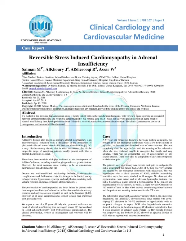
1 / 10
110 likes | 270 Views
Stress induced-Optical Effects in a Photonic Waveguide. Waveguide layers are grown at high temperatures. The materials have different thermal expansion coefficients, i. T = 1000 C. T = 20 C.

E N D
Waveguide layers are grown at high temperatures The materials have different thermal expansion coefficients, i T = 1000 C T = 20 C • Thermally induced stresses remain at the operating temperature resulting in a weakly birefringent material
Air Cladding (SiO2) Core (doped SiO2) Buffer (SiO2) Silicon Wafer (Si) • Variations in the z-direction are neglected thus reducing the problem to 2D • The optical core and planar waveguide layers are made of Silica (SiO2) which is deposited unto a Silicon (Si) wafer
Displacement constrained in x, and y -directions Displacement constrained in the y-direction • An exact perpendicular hybrid-mode wave formulation is used for the optical mode analysis • The 2D plane strain approximation with thermal loads is used for the structural part of the model Optical computational domain with PEC boundary conditions,
Relation between the refractive index and stress tensors Stress tensor nij = -Bijklkl Refractive index tensor, nij-n0Iij Stress-optical tensor nx = n0 – B1 σx – B2 [σy + σz] ny = n0 – B1σy – B2 [σz + σx] nz = n0 – B1σz – B2 [σx + σy]
Stress analysis • The extension of the layers in the x-direction is chosen to minimize the horizontal stresses
Refractive index Vertical birefringence Horizontalbirefringence • A constant horizontal birefringence means that the influence of the edges is reduced to a minimum
Mode analysis • We will study optical modes for a free-space wavelength of 1.55 m • Visualization of the power flow, also called the optical intensity or the Poynting vector, in the z-direction (out of plane direction)
The two lowest modes mode splitting
Mode analysis, higher eigenmodes Larger energy leakage compared to lower modes