Download
1 / 31
310 likes | 322 Views
This design project aims to evaluate the tritium breeding ratio, determine flux distribution, evaluate nuclear heating and radiation damage, and pursue sustainable fusion energy.

E N D
Nuclear Technology of the GT Fusion DEMO Reactor Andrew Rosenstrom, Nathan Morgenstern, Wes Crane, Stephen Johnston, Christian Maniscalco, Xianwei Wang Advisors: Dr. Stacey, Dr. Petrovic
Neutronics The design project will undertake the nuclear design (neutron transport, temperature distribution, stress analysis, radiation damage lifetime, tritium self-sufficiency) of this Fusion DEMO, consisting of the following: Objectives Evaluate the tritium breeding ratio and tritium self-sufficiency. Determine flux distribution throughout the blanket and at the magnet systems. Nuclear Heating Evaluate energy deposition in blanket to determine temperature distribution and heat removal. Conduct coupled thermal and stress analysis. Radiation Damage Determine the lifetime of magnet and breeding systems. Estimate replacement intervals of first wall and diverter.
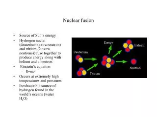
Pursuit of sustainable fusion energy began with plans for experimental power reactors once the deuterium-tritium fusion interaction was more closely studied in the later years of the 1970's 1980 1990 2000 2010 Background First plasma achieved in a tokamak reactor using magnetic confinement in JET (UK) Plans for the International Thermonuclear Experimental Reactor were set into motion JET Tokomak continues to produce record breaking amounts of power while its magnetic confinement design becomes the standard for future projects First instances of deuterium-tritium plasma making for a higher standard of power output alongside a more stable operation become standard Timetable for the future of the fusion DEMO project presented in 2004 to IAEA for construction to begin in 2024 and end 2033 looking to generate marketable power Start of building construction for ITER project in 2010 after agreement in 2006
Advancing design of the latest models of fusion reactors focuses on certain main components: • Tritium Breeding Blanket • The amount of tritium used in ratio to the amount of tritium produced by a breeding material is the Tritium Breeding Ratio (TBR) and is of high importance in making fusion viable • Lithium composites makes a strong tritium producer, and here will be in a ceramic mixture • Shielding Materials • Radiation resistant materials are necessary to durability, and have been researched to reveal Eurofer 97, or ODS Steel, as the best choice among others (Be, W) • Coolant • Among coolant options explored, water provides the most stable heat transfer State Of The Art
Motivation • Fuel for fusion is abundant in the form of deuterium that can be found in water, while tritium can be produced by the lithium/neutron reaction that will occur in the core. • Fusion energy is clean. It produces no greenhouse gases, only helium and a high energy neutron. Additionally, there are no dangerous fission products that are associated with most nuclear reactors. • Fusion reactors are inherently safe. Any malfunctions in the reactor will cause the plasma to cool and the reactions to cease. No meltdowns or runaway reactions will occur. 5
Scope • This project will only be to design a water cooled ceramic breeder blanket and will not consider other methods of cooling or breeding. • The neutronics modeling in MCNP will not consist of a detailed blanket module design. For simplicity the TBM will be treated as a homogenous mixture. • The tritium recovery system and external coolant systems will not be considered; however, the blanket modules will be designed with anticipation of their eventual removal and replacement. • Component lifetimes will not take into account damage created from transient plasma disruptions. The system will be assumed at steady-state. • Divertor lifetime will not consider charged particle flux from the convergence of magnetic field lines. • ANSYS will be used to simulate thermal/stress analysis, considering the cell with the maximum heat flux as determined by MCNP.
Design Basis Conceptual Design of a Water Cooled Breeder Blanket [2] Subcritical Advanced Burner Reactor [1]
Success Metrics • TBR ≥1.15 • Radiation Damage • Limits • Magnets - 2x10²² >1 MeV [n / m2][3] • Blanket Structure - 200 dpa • Significant Li Burnup will not occur within the lifetime of the reactor. • Graphite Shielding - N/A • First Wall - 200 dpa • Lifetime • First Wall: >20 Effective Full Power Years • Blanket: >20Yr • Temperature distribution within Li4SiO4 operational parameters. • 325 to 925 degrees celsius
Test Blanket Module Design Red - Graphite Shield Green - ODS Steel Blue - Homogenous Breeding Blanket a = 50 cm b = 5 cm c = 300 cm d = 100 cm
Coolant System Design Protection layer with the thickness of 3 mm Circular channels are used FW Finite Element ANSYS Model Blanket Coolant Tube Spacing
Tritium Breeding Blanket: Eurofer 97 [3]: Homogenous Material Composition
Tallies used: F2, F4 and F6 MCNP6 using the following equation to preform tally multiplication. In the equation φ(E) is the flux in particles/cm2 and R(E) is the response function from the MCNP cross-section libraries for a given tally multiplier. If the constant C is the particles generated per second, 5.326E20 and is multiplied by the atomic density in atoms per centimeter barn the results of the multiplication will be in reactions/cm3sec. Calculation of Critical Values Using MCNP6 Results
24 25 2 26 Flux On First Wall/Vacuum Vessel 27 6 28 19 29 20 21 34 22 33 32 23 31 36 30 35 37
Neutron and Photon Flux Distribution Photon Flux [p/cm2s] Neutron Flux [n/cm2s]
Flux at Magnet Systems Inboard Toroidal Magnet System • Flux of 8.7179E12 [n/m2s] with a uncertainty of 0.0168 of neutrons greater than 1 MeV • Would take 2.3566E9 seconds or 72 years of full power operation to reach fluence limit. Outer Toroidal Magnet Systems • Flux of 4.07E11 [n/m2s] with a uncertainty of 0.0125 of neutrons greater than 1 MeV • Would take 4.991E10 seconds or 1557 years to reach fluence limit.
24 25 2 26 Heating of the First Wall 27 6 28 19 29 20 21 34 22 33 32 23 31 36 30 35 37
Based on MCNP results, the blanket cell with the max heat flux is chosen to perform temperature calculation. Thermal boundary: inlet temp: 280°C, heat flux density: 0.3 MWm-2, heat deposition: 15.3 MWm-3 FW Fluid-solid coupling analysis: temp calculation outlet inlet Water temp distribution FW temp distribution
Boundary condition: water pressure 15 MPa, fixed at the end surfaces, symmetry constraint at the bottom surface The max stress is within the threshold, the deformation can be neglected FW Thermal/Stress Analysis: under water pressure Smax=56.3 MPa Total displacement Shear Stress
Boundary condition: water pressure, heat flux derived from fluid-solid coupling analysis The maximum shear stress is below the limiting stress value of 320 MPa at the first wall temperatures FW Thermal/Stress Analysis: under water pressure & heat flux Shear Stress Total Displacement Shear Stress On Armor
The large stress region (corner) is selected to carry out stress linearization; the membrane stress, bending stress, and thermal stress are determined. FW Thermal/Stress Analysis: stress linearization ×105 Path 1 Stress (Pa) ×10-2 Distance (m) The Path of Stress Linearization Stress Linearization
24 25 2 26 Radiation Damage: FW 27 6 28 19 29 20 21 34 22 33 32 23 31 36 30 35 37
Conclusion The crucial design criteria posed by the project have been met by the design of the tritium breeding blanket and coolant system design. • The lifetime of the magnets systems for the inboard and outboard toroidal magnets system are 72 and 1557 respectively. This is an adequate operational lifetime for a fusion reactor or any power plant. • The nuclear heating due to neutron and photon heating and coolant system design was such that the temperature of the breeding material was within the operational window defined by the literature. • The components such as the first wall and shielding all had adequate lifetimes to ensure the continuous operation of the reactor with minimal interruptions. • The tritium breeding ratio was sufficiently high to generate the tritium needed for the operation of a fusion reactor.
References • W. M. STACEY et al, “Resolution of Fission And Fusion Technology Integration Issues: An Upgraded Design Concept For The Subcritical Advanced Burner Reactor” Nuclear Technology, 2014. • S Liu, Y Pu, X Cheng, et al. Conceptual design of a water cooled breeder blanket for CFETR[J], Fusion Engineering and Design, 2014, 89: 1380-1385 • STACEY Fusion: An Introduction to the Physics and Technology of Magnetic Confinement Fusion Wiley New York (2010) • FERNANDEZ ET AL. “Reduced Activation Ferritic/Martensitic Steel Eurofer´97 as Possible Structural Material for Fusion Devices, Metallurgical Characterization on As-Received Condition and after Simulated Service Conditions” IAEA (2004)