1 / 0

Agenda for Week (1/28 & 1/30)

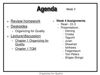
Agenda for Week (1/28 & 1/30). Learn about database design Vocabulary Modeling tool: Entity relationship diagram (ERD) Practical modeling concepts Do database design Practice creating ERD’s Primarily from “draftsman” perspective. Database Design.

eudora
Download Presentation

Agenda for Week (1/28 & 1/30)

An Image/Link below is provided (as is) to download presentation Download Policy: Content on the Website is provided to you AS IS for your information and personal use and may not be sold / licensed / shared on other websites without getting consent from its author. Content is provided to you AS IS for your information and personal use only. Download presentation by click this link. While downloading, if for some reason you are not able to download a presentation, the publisher may have deleted the file from their server. During download, if you can't get a presentation, the file might be deleted by the publisher.

E N D

Presentation Transcript


  1. Agenda for Week (1/28 & 1/30) Learn about database design Vocabulary Modeling tool: Entity relationship diagram (ERD) Practical modeling concepts Do database design Practice creating ERD’s Primarily from “draftsman” perspective
  2. Database Design Goal for the database design section of the class: Be able to design a “good” database for a business application. Objectives for this week: Know how to read, understand, and create a database model using a modeling tool - ERD’s. Know the process of completing a database design. Understand the structure and limitations of the relational model. Know how to identify and differentiate the required components of a database design.
  3. What is database design? Database design is the process of creating the structure or blueprint of stored data for an organization. The goals of database design are to produce a structure that: Stores data without redundancy; Can be changed relatively easily; and Stores all data required for organizational processing and decision making.
  4. Tasks in process of design Sample processes are discussed in Chapter 1 (or Chapter 2 of the 9th edition). Big picture: Decide what data are stored. Decide how data are related. Identify necessary constraints. Primary key. Foreign keys/Referential integrity. Check constraints. Document design decisions with a set of data models.
  5. Visualization Method: Spreadsheet (Data)
  6. Data design is documented with a data model Most commonly used data modeling tool is an entity-relationship diagram (ERD). An ERD contains: Entities. Attributes. Identifiers (primary key for each entity). Relationships. Cardinalities of the relationships. Foreign keys to support the relationships.
  7. Visualization Method: Data Model (Blueprint) This ERD is referred to as a “logical” ERD
  8. All About Entities Entities are nouns that describe the person, event, place, or thing about which we want to store data. The name of an entity is singular, not plural. Examples: customer, book, order, invoice, employee, supplier. An entity usually becomes a table in a database. An entity instance is a single occurrence of an entity (think a row in a table, or a record in a file).
  9. A bit about relationships Entities do not usually exist in isolation. A connecting line between two entities on an ERD represents a relationship. A relationship can be depicted as a diamond or as a simple line. A relationship is a natural business association existing between two or more entities. A relationship creates a business rule. A verb phrase describes the relationship.
  10. Cardinality of a relationship Cardinality is a constraint on the number of entity instances that participate in a relationship. Cardinality describes the minimum and maximum number of instances that one entity has with another entity in a relationship. Cardinality also describes whether the relationship is mandatory or optional. We use the crow’s foot notation to depict cardinality in our ERD’s in this class.
  11. Foreign Key A way of supporting the relationship between two tables. The primary key of one table is added to another table to link the two tables together. In a 1:M relationship, the primary key of the entity on the “1” side of the relationship is added to the entity on the “M” side of the relationship.
  12. Sample Data for 2 Entities
  13. New Business Rule!! A home can have more than one owner. How can that be expressed in the database? Must fit within the database rules: A table can have an unlimited number of rows. Rows can be added any time. A table has a fixed number of columns. Columns are declared when the table is created – can’t add new columns on the fly.
  14. This is a many-to-many relationship. The abbreviation is a M:N relationship
  15. Sample Data for New Rule
  16. Important Point A many-to-many relationship always produces data redundancy. The designer eliminates many-to-many relationships from the data design by creating an “intersection” entity. An “intersection” entity is a weak entity, also referred to as an “associative” entity because it is an entity that is associated with a strong entity.
  17. How to fix the redundant data problem??
  18. Strong entity A strong entity is an entity that exists whether or not there is a relationship between it and another entity. For example, in a health care application you probably want to store data about employees, regardless of whether an employee provides services to a patient at a clinic.
  19. Weak Entity An entity that relies on the existence of another entity. Does not exist in “real life” – is most often a data modeling requirement, rather than a real data requirement. Example on previous pages is called an “intersection entity” because it intersects two other entities and sub-divides a M:N relationship.
  20. Finishing up Exercise 1 Modify the ERD created for question #2 to include a real estate agent. Real estate agents represent owners in the sale of a home. A real estate agent has a unique agent identifier, a name, and a phone number. A real estate agent may represent more than one owner, and an owner may employ more than one real estate agent. On the other hand, a given home is represented by only one agent. An agent may represent more than one home, however.
  21. Deciding which business rules to capture… An agent could represent more than one owner, an owner could work with more than one agent. An agent could represent more than one home, a home has a single agent. Are both relationships important? Can each owner of a single home have a different agent?
  22. How do we move from a spreadsheet format to a relational database design?
  23. Moving from data to design Separate the attributes from the entities in your own mind. Identify the strong entities. Clarify which attributes “belong” with which entities. Define the relationships between the entities.
More Related