Download
1 / 12
120 likes | 311 Views
ECE 382 Lesson 13. Lesson Outline Peripherals Memory-Mapped IO Ports GPIO Multiplexing Admin Lab 2 GitHub report due COB Monday. Peripherals. What are Peripherals? MSP430G2xx Peripherals? MSP430 wikipedia : Watchdog Timer Universal Serial Communication Interface (USCI)

E N D
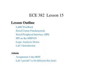
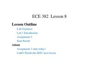
ECE 382 Lesson 13 Lesson Outline Peripherals Memory-Mapped IO Ports GPIO Multiplexing Admin Lab 2 GitHub report due COB Monday
Peripherals • What are Peripherals? • MSP430G2xx Peripherals? • MSP430 wikipedia: • Watchdog Timer • Universal Serial Communication Interface (USCI) • Implements SPI and I2C protocols • We'll use SPI to interface with the LCD in your black box • Pulse Width Modulation (PWM) • We'll use this later to drive the robot • Temperature Sensor • Multipliers • Capacitive Touch I/O • For working with touch screens, etc
Ports • What are Ports? Examples? • Your LaunchPad Board has… • Port 1, Pin 0 to Pin 7 • Port 2, Pin 0 to Pin 5 (where are pin 6 and 7?)
How do we talk to Ports? Do I/O? • Two classic methods • Memory-Mapped I/O (Motorola) • Port-Mapped I/O [or Isolated IO] (Intel) • Memory-Mapped I/O • I/O and memory SHARE the same address space • Advantage • Fewer instructions • Can use all addressing modes • Disadvantage • Lose memory to IO • Programmer mistakes • How to use • Mov #0x55, &P1OUT • Mov #0x55, &0x0021 • User’s Guide p 333, Table 8-2 • Watchdog Timer, page 341
How do we talk to Ports? Do I/O? • Port-Mapped I/O (Intel) • I/O and memory have their own separate address space • Advantage • Don't lose memory for IO. • Protects coder from mistakes. • Disadvantage • Need More Instructions (like In/Out) • More restrictive addressing modes • How to use • Out #0x55, &PORT1 • Does Port-Mapped cheat?
General Purpose Input Output (GPIO) • The registers used to configure GPIO are PxDIR, PxREN, PxOUT, and PxIN • PxDIRconfigures which pins are input and which pins are output • 1 corresponds to output, 0 to input • PxREN controls pull up / pull down resistors to avoid floating inputs. • Writing to PxOUT controls the output of each pin • PxINallows you to read the values on these pins Let's write a program that controls the onboard LEDs with the onboard push button bis.b #BIT0|BIT6, &P1DIR bic.b #BIT3, &P1DIR check_btn: bit.b #BIT3, &P1IN;push button is LOW on push jzset_lights bic.b #BIT0|BIT6, &P1OUT jmpcheck_btn set_lights: bis.b #BIT0|BIT6, &P1OUT jmpcheck_btn Any problem with this code?
Example Program Input was FLOATING! Low is ground, High is floating, so use a pull- _________? bis.b#BIT0|BIT6, &P1DIR ; output pin direction bic.b#BIT3, &P1DIR ; input pin direction bis.b#BIT3, &P1REN ; enable pin 3’s resistor bis.b#BIT3, &P1OUT ; make it a pull-up? (trick) check_btn: bit.b #BIT3, &P1IN jzset_lights bic.b#BIT0|BIT6, &P1OUT jmpcheck_btn set_lights: bis.b #BIT0|BIT6, &P1OUT jmpcheck_btn
Pitfall !!! • Anything wrong with this? • mov.b #0xff, P1DIR • What do these commands do? • mov.b#0b00001111, &P1DIR • bis.b#0b00001111, &P1OUT • mov.b #0xff, &P1OUT • mov.b &P1IN, r5
Multiplexing • Only 20 Pins !!! But want access to many more signals • Therefore, each pin shares several signals multiplexing • Use PxSEL1 and PxSEL2 to select signal for each pin • The details are in the MSP430G2x53 2x13 Mixed Signal MCU Datasheet.
Pitfall !!! Let's say I wanted to make the UCA0SOMI function available on P1.1: • ; 'from USCI' means this bit is set automatically by the USCI when enabled • bis.b #BIT1, P1SEL • bis.b #BIT1, P1SEL2
Inclass Exercise Modify this program so the two LEDs always have the opposite value bis.b#BIT0|BIT6, &P1DIR ; output pin direction bic.b#BIT3, &P1DIR ; input pin direction bis.b#BIT3, &P1REN ; enable pin 3’s resistor bis.b#BIT3, &P1OUT ; make it a pull-up? (trick) check_btn: bit.b #BIT3, &P1IN jzset_lights bic.b#BIT0|BIT6, &P1OUT jmpcheck_btn set_lights: bis.b #BIT0|BIT6, &P1OUT jmpcheck_btn