Download
1 / 16
160 likes | 293 Views
This lesson covers the essentials of serial communication, focusing on the Serial Peripheral Interface (SPI) using the MSP430 microcontroller. We will explore key concepts such as synchronous vs. asynchronous communication, advantages and disadvantages of serial communication, and how to control peripherals like an LCD display using serial ports. The lab will include a demonstration of setting up SPI, configuring clock parameters, and managing data transfer using the Universal Serial Communication Interface (USCI). Additionally, we will delve into subroutine optimization techniques.

E N D
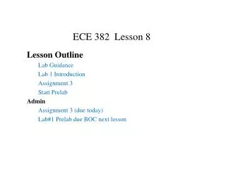
ECE 382 Lesson 15 Lesson Outline Lab#2 Feedback Serial Comm Fundamentals Serial Peripheral Interface (SPI) SPI on the MSP430 Logic Analyzer Demo Lab 3 Introduction Admin Assignment 4 due BOC Lab 3 prelab? (a bit different this time)
Lab#2 feedback What is wrong with this subroutine? Other Issues: pass-by-reference and pass-by-value Subroutine Header: Which is the best? Choice A ; Inputs: ; Outputs: Choice B ; Inputs: r10, r11, r6, r8 ; Outputs: r8 Choice C ;Inputs: r10 length of message r11 length of key • r6 address location of encrypted message r8 address location for decrypted message ;Outputs: RAM [@r8 to @(r8+r11)] decrypted results
What does this disassembled code do? 0000c0a2 <mystery_routine>: c0a2: 0d 4f mov r15, r13 c0a4: 0f 43 clr r15 c0a6: 0e 93 tst r14 c0a8: 07 24 jz $+16 ;abs 0xc0b8 c0aa: 12 c3 clrc c0ac: 0d 10 rrc r13 c0ae: 01 28 jnc $+4 ;abs 0xc0b2 c0b0: 0f 5e add r14, r15 c0b2: 0e 5e rla r14 c0b4: 0d 93 tst r13 c0b6: f7 23 jnz $-16 ;abs 0xc0a6 c0b8: 30 41 ret
Serial Communication • Lab#3: Using Serial port to control LCD Display • Parallel versus Serial? • Serial Advantages? • Serial Disadvantages?
Serial Communication • Lab#3: Using Serial port to control LCD Display • Parallel versus Serial? • Serial Advantages? • Simple interface – less hardware, less pins, less cost • Faster clock speed per wire (no “cross-talk”) • Longer Distance (no “cross-talk”) • Serial Disadvantages? • Slower • On-chip hardware to encode/decode serial signal
Serial Peripheral Interface (SPI) • Simple: with each clock cycle, a single bit is transferred from the MSB of one shift register to the other • Is this a half-duplex or full-duplex protocol? • Synchronous or Asynchronous protocol? • How many clocks to transfer a byte? • Signals • MOSI: Master Out Slave In • MISO: Master In Slave Out • SCLK: Clock • SS: Slave Select • TI renamed these: • MOSI = SIMO • MISO = SOMI
Serial Peripheral Interface (SPI) • Slave Select signal allows the master to potentially use the same interface to potentially interact with multiple slaves. It's usually active low
Serial Peripheral Interface (SPI) • Can we just tie SS low? • Configurable Elements: • Clock frequency • Clock polarity • Clock phase • On the MSP430: • MSB first or LSB first • you'll pretty much always want MSB first, which isn't the default • 8-bits or 7-bits per transmission • 7-bits is justified toward the LSB • 3-pin or 4-pin modes
Universal Serial Communication Interface (USCI) • On the MSP430: • Two Universal Serial Communication Interfaces (USCI), A and B • Can do multiple protocols (one is SPI), defined by configuration registers • UCA0 and UCB0 • datasheet - control registers (pp 435-448)
Universal Serial Communication Interface (USCI) • Step 1 • Setting the UCSWRST bit in the CTL1 register [16.4.2] resets the subsystem into a known state until it is cleared. All the registers will hold their default values. • Step 2 • Set the appropriate bits in the control registers to configure our signal the way we want. • Remember, you've got to set UCSYNC for the system to function! • CTL0 [bit 7 phase; bit 6 polarity; bit 3 master/slave; bit 0 UCSYNC = 1 ] [16.4.1] • CTL1 [bit 7&6 clock; bit 0 UCSWRST][16.4.2] • UCBRx [clock speed] [16.4.3 & 16.4.4] • STAT [16.4.5] • Step 3 • All the ports on our MSP430 are multiplexed! We need to set the PxSEL and PxSEL2 • Step 4 • Clear the UCSWRST bit in the CTL1 register - releases the system to operate.
Universal Serial Communication Interface (USCI) • Step 5 • Use the subsystem! • To send a byte, just write to the TXBUF register. [16.4.6] • To read a received byte, read from the RXBUF register. [16.4.7] • How do you know “you’ve got mail” or last transmission is done? • You've got to monitor the flags in the IFG2 register [16.4.9] to know when it's safe the send • TXIFG • Set when TXBUF is ready for a byte • Cleared on write • Just because the TXBUF is ready for another byte doesn't mean that the transmission is complete! It's double-buffered! • RXIFG • Set when RXBUF has received a complete character • Cleared on read • This is what you should monitor to determine a transmission has completed!
Example (loopback) bis.b#UCSWRST, &UCA0CTL1 bis.b #UCCKPL|UCMSB|UCMST|UCSYNC, &UCA0CTL0 ; don't forget UCSYNC! bis.b #UCSSEL1, &UCA0CTL1 ; select a clock to use! bis.b #UCLISTEN, &UCA0STAT ; enables internal loopback bis.b #BIT4, &P1SEL ; make UCA0CLK available on P1.4 bis.b #BIT4, &P1SEL2 bis.b #BIT2, &P1SEL ; make UCA0SSIMO available on P1.2 bis.b #BIT2, &P1SEL2 bis.b #BIT1, &P1SEL ; make UCA0SSOMI available on P1.1 bis.b #BIT1, &P1SEL2 bic.b #UCSWRST, &UCA0CTL1 ; enable subsystem send mov.b #0xBB, &UCA0TXBUF ; place a byte in the TX buffer wait bit.b#UCA0RXIFG, &IFG2 ; wait for receive flag to be set (operation complete) jzwait mov.b&UCA0RXBUF, r4 ; read RX buffer to clear flag jmpsend ; send another byte
Logic Analyzer • Sending 0xBB once (0x1011 1011) [MSB first!] • Note how the clock default state is high and data is read on the second clock edge - consistent with our settings.
Logic Analyzer Demo • Logic Analyzer is tutorial available here. • Let’s Measure SMCLK (P1.4) • Multiplexed? P1SEL1 & P1SEL2?
Measure SMCLK • Hook up the black Ground wire on Pod 1 to ground on the MSP430 • Hook up Pod 1 Wire 0 to P1.4 (SMCLK) • Sampling setup screen: set the sampling speed to be the fastest possible (once every 2ns) • Waveform screen and set the trigger on my signal to be falling edge • Run Single button • Drag markers to measure falling edge to falling edge of SMCLK bis.b#BIT4, &P1DIR bis.b#BIT4, &P1SEL forever jmpforever
Lab3 (in draft) • http://ecse.bd.psu.edu/cmpen352/lab/lab3/inlab3.html