Download
1 / 37
400 likes | 538 Views
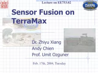
Lecture on EE753.02. Sensor Fusion on TerraMax. Dr. Zhiyu Xiang Andy Chien Prof. Umit Ozguner. Feb. 17th, 2004, Tuesday. MONO-VISION computer Linux. STEREO-VISION computer Linux. CAMERAS. CAMERAS. LADARs. Sensor and Sensor Fusion computer Linux. Radars.

E N D
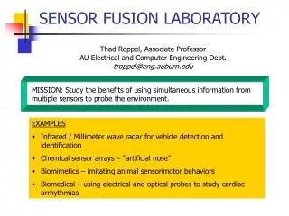
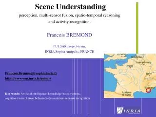
Lecture on EE753.02 Sensor Fusion on TerraMax Dr. Zhiyu Xiang Andy Chien Prof. Umit Ozguner Feb. 17th, 2004, Tuesday
MONO-VISION computer Linux STEREO-VISION computer Linux CAMERAS CAMERAS LADARs Sensor and Sensor Fusion computer Linux Radars Map and high level path planning computer Short distance sensors High level Control Low level Sensing Compass Low Level Control QNX INS GPS Internal sensors Alarm monitoring and heartbeat External switches Brake actuators Throttle Control Steering motor Shifting E-Stop System Overview
Laser Radar (LADAR) Radar Mono Vision Stereo Vision Sonar DGPS INS Position Fusion Sensor Fusion C O M P A S S High Level Sensor System Overview
Why Sensor Fusion? • Sensors have different perceptive ability against environment; • Sensors have different field of view; • Even with the same type of sensors, we can: • Enlarge the entire field of view by using more sensors; • Accumulate the information acquired at different time to achieve better perception.
GPS • GPS Receiver and Antenna
The Information available from GPS • 1. Position in the Geodetic Coordinates (latitude, longitude, Altitude) • 2. Rate information. (Horizontal Speed, orientation to the true north.) • 3. The GPS Precise Time.
GPS - Advantages • Advantages: • Satellite-based radio navigation system; • Provide information to the users of GPS receivers worldwide in all weather conditions, free of charge; • Reduces overall system costs by eliminating the need for a separate base station to obtain decimeter-level accuracy • Protects against shock, water, and dust, extending the life of the receiver • Virtually eliminates the effects of multipath using NovAtel’s patented Pulse Aperture Correlator™ (PAC) tracking technology
GPS - Features - Accepts OmniSTAR L-band differential corrections (subscription required) • Shock, water, and dust resistant • Three RS-232 serial ports capable of rates up to 230,400 bps • Power and communication status LED indicators • Field-upgradeable firmware
INS System • Dynamic Roll, Pitch Body to Earth Frame Angles • 3-Axis Vehicle Body Rates • 3-Axis Vehicle Body or Earth Accelerations
INS - Features • Fiber Optic Gyro Stability < 20°/hr • Fully Compensated Angular Rate and Linear Acceleration Outputs • SAE (Earth Coordinate) Navigation Frame • Automotive Compatible 10-30 VDC Input Supply • Analog & Digital Outputs
One Example Application of INS • Inertial systems are frequently used in actively stabilized platforms. Actively stabilized means that a series of motors and gimbals in conjunction with a inertial sensor work actively to hold the platform stationary. • Active stabilization systems are typically used to point cameras or antennae on a moving plane, helicopter, ship, train, or even RV. There are also cases where cameras permanently attached to the ground are stabilized for wind and vibrational forces.
Compass • The HMR3000 Digital Compass Module is a three-axis compass featuring 0.5 degree accuracy and a fluidic tilt sensor for +/- 45 degree compensation and digital serial bus interface (RS-485 or RS-232 options).
Why Fuse GPS/INS/Compass? • Accuracy. INS can lead to the unbounded growth of its error, even with the smallest amount of error in its measurements. This gives the rise to the need for an augmentation of the measurements by external aiding sources to periodically correct the errors. GPS can do that, with its bounded measurement error.
Why Fuse GPS/INS/Compass? (II) • Data Output Rate. The data output rate of GPS is 10 Hz at the most, which is insufficient for the positioning of a vehicle under autonomous control. On the contrary, the output of INS is much higher, even more than 100Hz on the digital signal output and no frequency limit on analog signal output. The integration of both can therefore satisfy the data output rate requirement.
Why Fuse GPS/INS/Compass? (III) • Data Availability. GPS is a line of sight, radio navigation system, and therefore GPS measurements are subject to signal outages, interference, and jamming, whereas INS is a self-contained, non-jammable system that is completely independent of the surrounding environment, and hence virtually immune to external disturbances. Therefore, INS can continuously provide navigation information when GPS experiences short-term loss of its signals.
Why Fuse GPS/INS/Compass? (IIII) • Compass can provide yaw, pitch and roll information continuously independent of other sensors. Although the data output rate is less than 20Hz, it can correct the yaw information integrated from INS yaw rate periodically.
DGPS Antenna Yaw Rate Yaw X Accelerometer COMPASS Pitch Rate X Accelerometer Pitch roll Rate Z Accelerometer Roll DGPS Receiver INS SYSTEM Position: X,Y,Z RS-232 Hardware Interface GPS Output PC Speed: Yaw Extend Kalman Filter Algorithm Vehicle Status: Position: X,Y,Z; Speed: ; Accelerator: ; Yaw, Pitch, Roll; Rate of Yaw, Pitch and roll. Fusion Algorithm of GPS/INS/Compass
Vision System • Road and Free Space Finding by Mono-Vision
LADAR System • SICK LMS30206 Outdoor Version
Performance of LADAR 1. Angular Resolution: 1° / 0,5° / 0,25° 2. Response Time (ms): 13 / 26 / 53 3. Resolution (mm) : 10 4. Systematic Error (mm mode): 35 5. Statistical Error (1 Sigma): 10mm 6. Max. Distance (m): 80 7. Transfer rate: 9.6/19.2/38.4/500 kBaud
Obstacle Detection by LADAR • LADAR can tell the distance between the obstacle and the center of the LADAR
Scanning vertically h P L W Some Scenarios for Vertical Scanning Laser (I) The minimum width and depth of the ditch can be decided by the wheel radius and the speed of the vehicle. The higher the Ladar is installed, the farther the ditch could be detected.
h L h Some Scenarios for Vertical Scanning Laser (II)
Radar System • Provides Information of objects in the lane up to 350 feet ahead. • Advanced forward looking Doppler radar (24.725 GHz), providing distance, relative speed. • Operate effectively night or day, in rain, fog, dust, or snow.
Ultrasonic Sensors • For short range obstacle detection.(Less than 5 meters.) • Accuracy affected by temperature, moisture, etc.
What kind of confliction may happen between sensors? • IN Data Layer: • same objects in the environment, their position declared from sensors may be different (I.e., one sensor tells the range of 30 meter while the other tells 28 meter); • In Decision Layer: • The decision of the observation may conflict with each other.(I.e, No Obstacle VS. Obstacle).
How to solve the confliction between sensors? (I) • How does the confliction happen? • Different perceptive character of sensors; • Range, accuracy, field of view, imaging sensor VS. range sensor, etc.. • Changing of the surrounding environment; • False data input; • Thresholds on processing algorithms; • Different algorithms used.
How to solve the confliction between sensors? (II) • Measures to deal with the conflictions: • For data layer: • Using Target Tracking techniques (Extend Kalman Filter); • For decision layer: • Assign a confidence to each decision made by the preprocessing of each sensor; • Deduce the final decision with a deliberately designed Deducing Table (Evidence Theory based deducing).
-50m North 50m Vision Map Laser Map East 50m -50m High confidence of occupy High confidence of empty Low confidence of occupy Unknown area Map for High Level Sensor Fusion Type of the cells: ROD COV POB NOB MOB UKN
Map initialization Get Mono-Vision Information at Fusion map movement according to the GPS displacement between and Discard cells outside the map and give initial values to newly shift-in cells Broadcast confidence value to neighboring cells according to the model of position errors. (Gaussian noises) Get new Observations from Stereo Vision, LADAR, Radar and Sonar modules. Transforming the coordinates of different sensor modules to Sensor Map coordinates by using the calibration parameters. Multi-sensor calibration Fusing the Sensor Map into the Fusion map by using the Dempster-Shafer Evidence theory. Algorithms for Fusion Map Updating
Information from Sensor Map Information from Fusion Map ROD COV POB NOB MOB UKN ROD ROD (1) COV if (a) ROD if (b) (1) POB if (g), results (3); ROD if (h), results (5). NOB if (g), results (3); ROD if (h), results (5). MOB (3) ROD (2) COV ROD if (a) COV if (b) (1) COV (1) POB if (g), results (3); ROD if (h), results (5). NOB if (g), results (3); COV if (h), results (5). MOB (3) COV (2) POB ROD if (e), results (3); POB if (f), Results (4). COV if (e), results (3); POB if (f), results (4). POB (1) NOB if (c) POB if (d) (1) MOB (3) POB (2) NOB ROD if (e), results (3); NOB if (f), results (4) COV if (e), Results (3); NOB if (f), Results (4). POB if (c) NOB if (d) (1) NOB (1) MOB (3) NOB (2) MOB No prediction exists in the fusion map, replaced by UKN. UKN ROD (3) COV (3) POB (3) NOB (3) MOB (3) UKN (3) Deducing Table(I)
Summary • By sensor fusion, the complementary information from different sensors are fully and best combined; • Information acquired at different time is accumulated; • Sensors are integrated together and a best decision was made upon that.