Download
1 / 15
150 likes | 269 Views
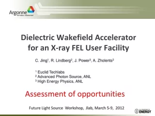
Development of an X-band Dielectric PETS. C. Jing, Euclid Techlabs / ANL. HG Workshop, May. 2011. OUTLINE. Motivation Previous Experiences on the dielectric based wakefield power extractors Development of an X-band Dielectric PETS. Motivation.

E N D
Development of an X-band Dielectric PETS C. Jing, Euclid Techlabs / ANL HG Workshop, May. 2011
OUTLINE • Motivation • Previous Experiences on the dielectric based wakefield power extractors • Development of an X-band Dielectric PETS
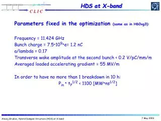
Motivation • CLIC PETS is one of the key components in the CLIC TBA scheme. According to the 2008 CLIC design parameters, 71568 PETS units total are needed for this 3 TeV machine, contributing a large portion of the overall cost. A low cost wakefield power extractor with the same parameters as PETS will be attractive. • Dielectric based wakefield power extractors, which can be inexpensively built, have been experimentally demonstrated in high power, short pulse conditions. We like to find out their performances in the CLIC required 240ns, 140MW rf pulse.
Dielectric-lined Waveguide to Slow the Wave Dielectric loaded waveguide can slow the RF wave for acceleration like the conventional disk-loaded waveguide. Low-loss dielectric materials bring promise to this kind of structure. • Advantages: simplicity of fabrication • potentially higher breakdown threshold • low surface field enhancement • Easy deflecting mode damping • Challenges: Multipactor Ez Er Electric Field Vectors (TM01) Hphi vacuum dielectric
Previous works C-Band Power extractor (2008) Ka-Band Power extractor (2009) • 15ns,1MW & 6ns, 20MW 26GHz rf pulse have been demonstrated in the current AWA beamline. • 148MW are expected with an improved beam control in the present AWA beamline. • 30ns,1MW & 6ns, 40MW 7.8GHz rf pulse have been demonstrated in the current AWA beamline. • 20ns 500MW are expected with the upgraded AWA beamline. 44MW generated 40MW extracted Downconverted signal 11.44+14.576=26.016 GHz
Development of the 12GHz Dielectric PETS • Design 12GHz dielectric PETS; and build an 11.424GHz version of dielectric PETS. • High power rf test 11.4GHz version structure at SLAC ASTA (we like to thank Sami’s group in advance ). • Build 12GHz dielectric PETS with information obtained in Step 2. • Beam test at CLIC. funded by DoE 2010 SBIR program Phase I. Submitted to DoE 2011 SBIR Phase II.
12GHz Quartz-Based Power Extractor Using CLIC Parameters: σz=1mm, Q=8.4nC, Tb=83ps
Design of a 12GHz Quartz-Based Power Extractor (thanks to Igor Syratchev) beam Connected to rf coupler
Design of a 12GHz Quartz-Based Power Extractor (by Igor Syratchev) Note: The peak magnetic field is 78.7 kA per 135 MW rf input 1.3C pulse heating.
11.424GHz version dielectric PETS for high power rf test Beadpull Result Low field in the 23cm DLA section
Summary • The 1st step, building a 11.424GHz version D-PETS, has been done. • We plan to high power rf test it at SLAC and explore the possible issues. • The rest of work has been applied for 2011 DoE SBIR Phase II funding.
Simple cooling <0.5dB Insertion loss~200W average power dissipation per 240ns 135MW rf input, 60Hz <1 C temperature gradient with good contact cooling.