Suspension
Suspension. Outline. Introduction Suspension components Suspension type examples Solid axle Double Wishbone MacPherson Strut Introduce basic geometry. Suspension Purpose. Isolate passengers and cargo from vibration and shock Improve mobility Improve vehicle control. Basic Terminology.


Suspension
E N D
Presentation Transcript
Outline • Introduction • Suspension components • Suspension type examples • Solid axle • Double Wishbone • MacPherson Strut • Introduce basic geometry
Suspension Purpose • Isolate passengers and cargo from vibration and shock • Improve mobility • Improve vehicle control
Basic Terminology • Sprung Mass • Mass of all components that do not move much when suspension is displaced. (given the frame as a fixed reference) • (Frame, engine, passengers, etc,) • Some suspension components are actually partially sprung mass
Basic Terminology • Unsprung Mass • Mass of components that move when suspension is displaced • Minimizing the unsprung mass allows for more optimal suspension operation
Basic Terminology • Bump • Vertical displacement of entire sprung mass
Basic Terminology • Roll • Front View angular rotation of the sprung vehicle mass
Basic Terminology • Pitch • Side View angular rotation of the sprung vehicle mass
Basic Terminology • Roll Center • Center at which the sprung mass pivots about during a roll situation (lateral acceleration) • This is a dynamic point: moves around throughout suspension travel
Basic Terminology • Pitch Center • Center at which the sprung mass pivots about during a Pitch situation (fore/aft acceleration) • This is a dynamic point: moves around throughout suspension travel
Basic Terminology • Camber • Front View tilt of the tire. • Leaning the top of the tire inboard adds negative camber
Basic Terminology • Toe • Top view angle of the tire in a static situation • Turning the front of the tire in is referred to as adding “toe in” • Important for both front and rear tires
Basic Terminology • Steering Axis • Axis about which the wheel/Tire rotate about during steering inputs • Also known as “King Pin Axis”
Basic Terminology • Caster Angle • Side view tilt of the steering axis. • Creates camber change with steering input • Creates a restoring force for centering steering wheel
Basic Terminology • Caster Trail • Side view distance from the steering axis ground plain intersection and the contact patch center point • Creates a restoring force for centering steering wheel
Basic Terminology • Scrub Radius • Distance From which the ground plain intersection of the Steering axis and the center of the tire contact patch • Large effect on drivers feel and steering effort
Basic Terminology • Steering Arm • Line between the steering axis and there steering linkage“tie rod”
Basic Terminology • Bump Travel • Vertical distance wheel is able to move up from static position, with reference to vehicles sprung mass • Droop Travel • Vertical distance wheel is able to move down from static position with reference to vehicles sprung mass
Passenger Comfort The perception of vehicle comfort is very subjective. Much depends on the cabin conditions. The main objective of the designer is to minimize the rate of change of acceleration (jerk).
Trophy truck video • Front Independent double wishbone Suspension • Rear Solid axle • High horse power vehicle
Baja Buggy • Front Independent double wishbone Suspension • Rear Independent double wishbone Suspension • Light weigh low horsepower vehicle
Extreme mobility • Control in extreme maneuvers
Simplified Quarter Car Model • Two Degree-of-Freedom System • However the longitudinal and lateral stiffness of most suspension cannot be totally disregarded
Simplified Half Car Model • Two Degree-of-Freedom System • However the longitudinal and lateral stiffness of most suspension cannot be totally disregarded
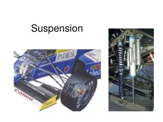
Components of Suspension • Tire • Linkage • Bearings, Bushings • Springs • Dampers • Sprung / Unsprung Mass
Tire • Acts as both a spring and a damper • These rates are affected by air pressure and tire construction.
Pivot Joints • Spherical & Roller bearings • High performance applications • Minimal Compliance • High Precision • Low Stiction/Friction • Bushings • Low Cost • Offers compliance
Spring Types • Leaf Springs • Used in many early applications • Internal friction provides damping • Provide Fore/Aft/Lateral location for the axle • Heavy • Prone to weaken over time
Spring Types • Torsion Bars • Little to no internal damping • Low cost • Often difficult to package
Spring Types • Coil Springs • Little to no internal damping • Low cost • Compact Size • Used in many Suspension types
Solid Axle Suspensions Applications: -Pick Up Trucks (Rear) -Stock Cars (Rear) -Rock Crawlers (Front & Rear)
Advantages • Fewer Individual Components • Easier to cheaply manufacture and assemble • Simplified drivetrain layout • High Load Capacity • Axle Components are protected • Can use leaf or coil springs • Also can accept many different types of linkages to gain desired geometry • Solid wheel attachment • Minimal alignment eminence
Disadvantages Disadvantages: • Higher Unsprung Weight • Can lead to “wheel hop” • Axle wrap when in a leaf spring configuration • High Roll Center Height • Not an Independent Design • Corners are coupled • Fixed Camber Angles
Camber Change • The diagram below shows how the camber is statically fixed, and does not change in rebound • The middle diagram shows how the camber of the two wheels are linked to one another
Solid axle adjustability • As far as the static characteristics of the suspension the camber and castor are preset in the manufacturing of the axle housing • However the dynamic characteristics of the suspension are highly adjustable with various forms or bar linkages • There are many different linkage designs for a solid axle ranging from leaf springs to multi-link suspension systems
Double Wishbone Suspension With Unequal Length Upper and Lower Arms Found On: -Stock Cars (Front) -Corvettes (C5 &C6) (Front and Rear) -Honda Civics (‘88-’00) (Front) -Most Modern Sports Cars
Advantages • Arguably the best handling suspension design • Wheel gains negative camber in bump • Low Unsprung Weight • Packaging does not compromise styling • Low Height • Many different geometry characteristics possible • Designer can design suspension with minimal compromises • Infinite adjustability, with the most ease • Vehicles roll centers can be placed almost anywhere
Disadvantages • More expensive • More components to make and assemble • Alignment and fitment are critical to vehicle performance, large area of adjustment • Tolerance of parts must be smaller • Requires constant alignment checks for optimum performance • More complex • Design often becomes more complex because all suspension parameters are variable • Frame has to be able to pick up a-arm inboard points • Tire scrub occurs with vertical wheel displacement • However this can be minimized during design
Double Wishbone Tuning • The double wishbones complexity enables it to be adjusted quite readily • The suspension geometry can be adjusted in two distinct ways • Move the location of the inner Chassis attachment points • Adjust the inclination of the upright and the pick-up locations on the upright • The camber, castor, roll center, etc…. can all be individually adjusted on this type of suspension relatively easily.
Suspension Types: MacPherson Strut • Invented by Earl S. MacPherson • First used on the 1951 Ford Consul • Ford held the patent for the Macpherson strut system by many rival companies invented similar systems to avoid Ford royalties
Suspension Types: MacPherson Strut Advantages • Low production costs • Stamped construction • Preassembled • Strut body carries spring assembly • Compact • Simple mounting and no need for an upper control arm • Simplicity • Reduction in fasteners and alignment of vehicle suspension components.
Suspension Types: McPherson Strut Disadvantages • Large camber variation • Body roll and wheel movement contribute to camber attitude • Vertically tall mounting position • This compromises vehicle styling • Rough ride • Some ride comfort may be lost, as it is hard to move smoothly because of bending input force • Dangerous replacement • The spring must be compressed and assembled on the strut body, this causes the handling of a charged spring.
Associated forces in the strut • Since the strut serves as the upper control arm as well as the damper it is required to provide the force to hold the wheel at the desired camber attitude.
Adjustment of MacPherson Strut • Since the strut governs the King pin axis as well as the camber of the tire, these two parameters are linked • The adjustability of the MacPherson strut is limited, due to its simplicity • Most adjustability of the suspension is achieved by modifying the location of the upper strut mounting location.
Suspension Types: MacPherson Strut • MacPherson Struts are widely used on a variety of cars today from the everyday road car to world class race cars