Comprehensive Guide to HVAC Systems: Design, Types, and Components
1.2k likes | 1.27k Views
This article provides an in-depth overview of HVAC systems, focusing on design principles, system types, and key components like chillers, air handling units, and filtration systems. Learn about energy efficiency, environmental impact, and maintenance considerations.

Comprehensive Guide to HVAC Systems: Design, Types, and Components
E N D
Presentation Transcript
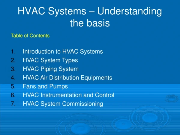
HVACSystems–Understanding thebasis TableofContents IntroductiontoHVACSystems HVACSystemTypes HVACPipingSystem HVACAirDistributionEquipments FansandPumps HVACInstrumentationandControl HVACSystemCommissioning
IntroductiontoHVACSystems Thisarticleintroducestheheating,ventilatingandair-conditioning (HVAC)systems.TheprimaryfunctionofHVACsystemsistoprovide healthyandcomfortableinteriorconditionsforoccupants;well- designed,efficientsystemsdothiswithminimalnon-renewable energyandair,andwaterpollutantemissions.
IntroductiontoHVACSystems ThepurposeofHVACdesignisbothhighindoorairqualityandenergy efficiency.Thesedualconsiderationsrequireanintegrateddesign approach.Rigsheating, ventilation,andairconditioning system(HVAC)createsaclimate thatallowsformaximumcomfortby nsatingforchangingclimatic ons. ccoompempe ccoondnditi Thoughmorecostlytoinstallandmorecomplicatedtooperate,achillerplant offersanumberofbenefitsoveralargenumberofindividualpackaged coolingunits,includinggreaterenergyefficiency,bettercontrollability, cheaperoverallmaintenance,andlongerlife.Usingacomprehensive approachtobuildingdesign,designersaroundtheworldhavesucceededat creatinghighlyefficientair-conditioningsystemsthatprovideexcellent comfortatsignificantsavings.
IntroductiontoHVACSystems Heating,ventilatingandair- conditioning(HVAC)systems reducetheenvironmental impactofrigs/buildingsinseveral keyways.Themostimportant functionofaHVACsystemsis toprovidetherig/buildingsoccupants withhealthyandcomfortableinterior conditions.Acarefullydesigned,efficient systemcandothiswithminimalnon- renewableenergyandairandwaterpollutantemissionstominimizethe environmentalimpact. Coolingequipmentthatavoidschlorofluorocarbonsandhydro- chlorofluorocarbons(CFCsandHCFCs)eliminatesamajorcauseof damagetotheozonelayer.
IntroductiontoHVACSystems EventhebestHVACequipmentandsystemscannotcompensatefora faultyrigdesign.Problemsofthistypecauseinherentlyhighcoolingand heatingneedsandconsumeunnecessaryresourcesandshouldbe correctedifpossible.Conservationofnon-renewableenergythroughan intelligentarchitecturaldesignoffersthegreatestopportunityforsavings. Themostimportantfactorsinthesedesignsarecarefulcontrolofsolargain, whiletakingadvantageofpassiveheating,daylighting,naturalventilation andcooling.Thecriticalfactorsinmechanicalsystems'energyconsumption -andcapitalcost-arereducingthecoolingandheatingloadstheymust handle.
HVACSystemTypes TypesofSystemDesigns-Thereareseveralmajorheating,ventilating,andair conditioningsystemtypesinwidespreadusetoday.Theseareairsystems,hydronic andsteamsystems,andunitarytypesystems.Mostsystemsinusetodayfallintooneof thesecategories,orareacombinationorvariationofthem.Eachtypeofsystemhas advantagesanddisadvantages. Aircooled -AircooledChillers
AirCooledChillerAdvantages • Lowerinstalledcost • Quickeravailability • Nocoolingtowerorcondenserpumprequired • Lessmaintenance • Nomechanicalroomrequired
WaterCooled • SeaWatercooledChillers • FreshWatercooledChillers
Water-CooledChilleradvantages • Higherefficiency • Customselectioninlargersizes • Largetonnagecapabilities • IndoorChillerlocation • Longerlife
Air HandlingSystems Purposeofanairhandlingsystem Air Handling System Room With Defined Requirements Supply Outlet Air Air
Objectives In the following slides, we will study the components of air handling systems in orderto: Become familiar with thecomponents Know theirfunctions Become aware of possibleproblems
Mainsubsystems Exhaust airtreatment Fresh airtreatment Terminal airtreatment (make-upair) + at production roomleve Room/Cabin Central air handlingunit
Overviewcomponents Exhaust AirGrille Flow ratecontroller Silence Fan Filter r Weatherlouvre Controldamper + Heater Humidifier Prefilter Terminalfilter SecondaryFilter Cooling coil ProductionRoom with Heating droplet coil Re-circulated air separator
Components(1) Topreventinsects,leaves, dirtandrainfromentering Weather louvre Silencer • Toreducenoisecausedbyair circulation • Automatedadjustmentof Flowrate controller volumeofair(nightandday, pressurecontrol) Control Fixedadjustmentofvolume ofair damper
Components(2) Toheattheairtotheproper temperature Heatingunit Tocooltheairtotherequired temperatureortoremovemoisture fromtheair Coolingunit /dehumidifier Tobringtheairtotheproper humidity,iftoolow Humidifier Toeliminateparticlesofpre- Filters determineddimensionsand/or micro-organisms Totransporttheair Ducts
Airtypes + Exhaust air Fresh air (make-upair) Supply air ProductionRoom Return air (re-circulated)
Filterclasses Dustfilters Standard Aerosol Coarse Fine Dp > 10 µm 10 µ m > Dp > 1 µm G1 -G4 F5 -F9 H 11 -13 U 14- 17 EN 779Standard EN 1822Standard
HEPA or tertiaaryfilter Primarypanel filter Secondary filter
Ductheaters RoomHeters Silensers
Volumecontroldamper FireDampers Dryair Humid room air Adsorberwheel AHU withfan VariableSpee Controller d Regenerationair Humid roomair FilterPressure Gauges Airheater De-humidification
Regulationofroompressure–pressure differentialsconcept Roompressure gauges Room pressure indicationpanel Annex 1,17.26
Pressurecascadeinjectables Protectionfrommicro-organismsand particles Ro om1 Ro om2 Ro om3 A L F 30Pa 60Pa 45Pa D Air L o c k 45Pa Air L o ck B C 15Pa Air L o ck 30Pa P a s s a ge D 0Pa Not e: Di r ect i onof door opening r el at i vet oroom pr es s ure
Pressure cascade solids Protection fromcross-contamination Ro om1 Ro om2 Ro o m3 15Pa 15Pa 15Pa Air L o ck Air L o ck Air L o ck 30Pa 0Pa E P a s s a ge 15Pa Not e: Di r ect i onof door openi ngr el at i vetor oom pr es s ure
HVACAirDistributionEquipments Diffusers 4WayDiffusers TwoWayDiffusers OneWayDiffuser RoundDiffusers
Fans andPumps • Contents • FanDesign • FanPerformance • Fan-ductSystems • DuctConstruction • AirDuctDesign
FanDesign • Commontypesoffans • Centrifugalfans:radial,forwardcurved,air foil(backwardcurved),backwardinclined, tubular,roofventilator • Axialfans:propeller,tube-axial,vane-axial • Fanarrangements • Motorlocation,airdischargeorientation,drive traintype(directdriveorpulleydrive) • Centrifugal:singlewidthsingleinlet(SWSI), doublewidthdoubleinlet(DWDI)
AXIALFANS CENTRIFUGALFANS Centrifugal and axial fancomponents
AXIALFANS Propeller Tube-axial Tube-vane
CENTRIFUGALFANS Tubular centrifugalfan Centrifugal roofventilator (* Note the airflow paths and impellerdesign.)
FanPerformance • Majorparameters • Fanvolumeflowrate(m3/sorl/s),Vf • FantotalpressureΔpttf,fanvelocitypressure • pvf&fanstaticpressureΔpsf(Pa) • Fanpower&efficiency • Fanpowerorairpower(W)=ΔptfxVf • Fanpowerinputonthefanshaft(brake horsepower),Pf • Fantotalefficiency:ηt=ΔptfxVf/Pf Combinedaerodynamic,volumetric&mechanical efficiencies • Fanstaticefficiency:ηs=ΔpsfxVf/Pf • Airtemp.increasethroughfan,ΔTf=Δptf /(ρcpaηt)
Fan performancecurves Totalpressure Staticpressure Fan totalefficiency Fan staticefficiency Fan powerinput Velocitypressure Volume flowrate
FanPerformance FanLaws Speed(n) Volumeflow(V) Totalpressureloss (Δp) Airdensity(ρ) Forairsystemsthat aregeometrically& dynamicallysimilar: (D=impeller diameter) c.f.:pumplaws
CENTRIFUGALFANS Velocity triangle at the blade inlet and outlet of a centrifugalfan
FanPerformance • Majorissuescausingenergylossestoa centrifugalfan: • Circulatoryflowbetweentheblades • Airleakageattheinlet • Frictionbetweenfluidparticlesandtheblade • Energylossattheentrance • Partiallyfilledpassage
Operating characteristics for a backward-curved centrifugalfan


