Timers and Interrupts
190 likes | 282 Views
Timers and Interrupts. Avi singh Kevin jose piyush awasthi. Recap. Registers. Software needed. AVR STUDIO. CVAVR. Extreme Burner AVR. Timers. 8-bit register. Values starts from 0 and goes up to 255. Timer value increases by 1,after each period .

Timers and Interrupts
E N D
Presentation Transcript
Timers and Interrupts Avisingh Kevin jose piyushawasthi
Software needed AVR STUDIO CVAVR Extreme Burner AVR
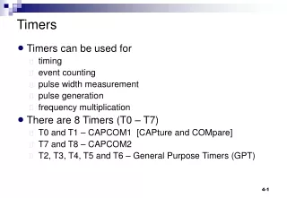
Timers • 8-bit register. • Values starts from 0 and goes up to 255. Timer value increases by 1,after each period. • (The standard issue MCU for Techkriti ‘15 will be Atmega16 which has a 16-bit clock register also. We will cover the theory of timer wrt 8 bit registers for the sake of clarity and ease of representation but all that is subsequently discussed can be applied to 16 bit registers with little or no modification) • When the timer reaches its maximum value, in the next cycle, its value becomes 0 again and the process repeats itself. • The timer frequency can be factors of the base frequency of the MCU. • This process is independent of the CPU.
Simple Statistics • Maximum value of timer is n and clock period is t, then: 1. Timer period = t 2. Timer cycle period = (𝑛+1)×𝑡 3. Frequency of timer (f) = 1/𝑡 4. Frequency of timer cycle = 1/(𝑛+1)×𝑡
Timer Modes • A timer works in three modes: Normal, CTC and PWM • Normal mode: Timer starts at zero, goes to maximum value and then resets itself • CTC (Clear Timer on Compare), clearly the timer starts at zero as usual, but instead of resetting after maximum value, it resets after reaching value specified in OCR register • PWM(Pulse Width Modulation) can be used to obtain analog values at the pins
Suppose you need to check for a condition A while running another condition B while(1){ ---- -> if (Event A == true) ---- -> // print event A has occurred ---- ---- ---- -> Event B ---- ---- } Do you see the problem in this approach?? -> Suppose Event A happens here
A better Solution: Interrupt • Interrupts means causing a break in a continuing process. • We execute the Event B in a normal while(1) loop. . while(1){ --- --- EVENT B --- --- } . • We will consider the occurrence of event A as an interrupt
Interrupts . while(1){ --- --- EVENT B --- --- } . handleA(){ . --- } // print event A has occurred We execute the required code in handler of event A
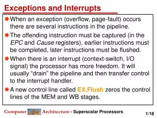
More on Interrupts • Interrupts are special events that can “interrupt” the normal flow of a program. • Whenever an Interrupt is called, the processor stops the normal program, handles the interrupt, and then resumes its normal work. • There are two types of interrupts: • External • Internal
External Interrupts • The controller monitors the input at the special pins INT0 and INT1, whenever external interrupt is set on. • We can configure the program to call an external interrupt whenever any of the following conditions are met. • Rising Edge • Falling Edge • Any change • Low level
Internal Interrupts • The internal interrupts are called when different specific conditions are met by the timer value. • Timers can generate certain interrupts: two, to be precise. • These are called OVERFLOW interrupt and COMPARE MATCH interrupt.
Overflow interrupts • An overflow interrupt is generated when the timer exceeds its maximum value and resets to 0. • The interrupt may or may not have a handler. In either case, the timer continues to run; remember: timers are independent of the CPU. • Suppose a timer of maximum value n has a time period t (also called as clock period). • Then : 1. Timer cycle frequency = 1/(𝑛+1)×𝑡 2. OVERFLOW interrupt frequency = 1/(𝑛+1)×𝑡 • If OVERFLOW interrupt is enabled, then an interrupt is generated in every cycle.
Compare Match Interrupt • A compare match interrupt is called when the value of the timer equals a specific value, set by the user. • This value is set by setting the value of OCR register. • Before incrementing, the value of the timer is compared to OCR. If the two are equal, a COMPARE MATCH interrupt is generated. • Suppose a timer of maximum value n has a time period t (also called as clock period). Then : 1. Timer cycle frequency = 1/(𝑛+1)×𝑡 2. COMPARE MATCH interrupt frequency = 1/(𝑛+1)×𝑡 • If COMPARE MATCH interrupt is enabled, then an interrupt is generated in every cycle.
Timers and Interrupts • All three timer modes differ in the response of the controller to the interrupts generated • OVERFLOW and COMPARE MATCH interrupts generated as normal in NORMAL timer mode • Compare match interrupt if enabled will be generated but not overflow interrupt (Why?)
Accelerometer • For Electromaniathis year, the standard issue board will be one based on an Analog 3-Axis MEMS Accelerometer • Poll values using Analog Input pins and scale appropriately to acquire the acceleration due to gravity on each axis and hence orientation • Refer to the datasheet for scaling information
Contact Us Kevin Jose 366 / Hall 2 kevinj@iitk.ac.in8127762331 Avi Singh A-129 / Hall 10 avisingh@iitk.ac.in8853544535 PiyushAwasthi150/Hall 2 piyushst@iitk.ac.in9616384444