Download
1 / 21
230 likes | 408 Views
Learn about interrupt-driven I/O, advantages, disadvantages, steps for handling interrupts, timer/counter functionalities, setting timer intervals, using interrupts to control LED blinking, and handling the watchdog timer in microcontrollers.

E N D
Interrupts (1) • Interrupt-driven I/O uses the processor’s interrupt system to “interrupt” normal program flow to allow execution of an I/O service routine • An interrupt is like a hardware-initiated subroutine call
Interrupts (2) • Advantages • Immediate response to I/O service request • Normal execution continues until it is known that I/O service is needed • Disadvantages • Coding complexity for interrupt service routines • Extra hardware needed • Processor’s interrupt system I/O device must generate an interrupt request
Basic Steps for an Interrupt (1) • An interrupt cycle begins at the next fetch cycle if: • Interrupts are enable (GIE = 1) • Interrupt request is active (I=1) • Program counter (PC) is saved on the stack • PC is loaded with address of interrupt service routine (ISR) • Different schemes for determining this address • Fixed location 0x0004 on the PIC processor
Basic Steps for an Interrupt (2) • Interrupt service routine executes • Saves any registers that will be altered so that normal program flow is not disturbed • Performs input and/or output operations to clear the interrupt request • Restores saved registers • Returns • Normal execution resumes
Example Pseudo code for an ISR ISR: save register(s) if (IN_RDY == 1) input data if (OUT_RDY == 1) output data restore register(s) return
Example Error if Registers are not Saved before Executing ISR
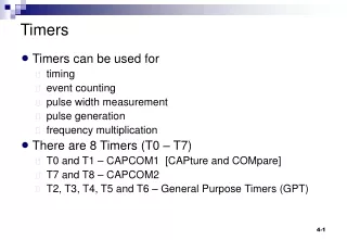
Determining Timer Settings Consider the “wait for 500ms” for LED problem… • Fosc = 4 MHz, internal timer can be driven by Fosc/4 = 1MHz • To have a 500ms interrupt on overflow interval, desired scale = 500ms/1μs = 500,000 • Maximum scale provided by Timer0 is 256*256=65,536 • Probably we can set up an interrupt interval shorter than 500ms, say Mms, then toggle the LED after every Ninterrupts, where M*N = 500. • The possible value of M has constraints. It is helpful to express the needed scale in terms of its prime factors, then allocate these among the prescaler, PR and the TMR0 register. • let’s try M=4 and N=125 for this example.
Initialize the Timer0 Desired scale for 4ms timing is 4ms/1μs = 4,000. Play with the math we have 32*125 =4,000 In order to get an exact 4 ms timing, we’ll need to set the timer as follows: PS2 PS1 PS0 =100 ; set prescaler to 32 TMR0 = 256-125 =131 ; initialize TMR0 T0IF = 0 ; clear timer0 interrupt flag TOIE =1 ; enable timer0 interrupt
Timer0 Initialization Code InitTmr0 bcf STATUS, RP1 ;select bank 1 bsf STATUS, RP0 movlw B’11010100’ ; set up OPTION, prescaler and timer0 resources movwf OPTION bcf STATUS, RP0 ; select bank 0 movlw D’131’ movwf TMR0 ; initialize TMR0 bcf INTCON, T0IF ; clear Timer0 interrupt flag bsf INTCON, T0IE ; enable Timer0 interrupt source bsf INTCON, GIE; enable global interrupts return
“Wait for 500ms” --- Use Timer • Since our Timer is set to overflow every 4ms, waiting 4ms really means waiting until the timer overflows. We will write an interrupt service routine to handle the timer overflow in a future class. Now we assume that in the interrupt service routine (ISR), BLNKCNT is decremented by 1 each time an overflow occurs. • Waiting 500ms means waiting timer overflow 125 times, which is counted by BLNKCNT. Five00Ms movlw 124 ; initialize BLNKCNT to 124, why??? movwf BLNKCNT ; BLNKCNT is a variable wait500 btfss BLNKCNT, 7 ; wait for 00000000 to 11111111 change goto wait500 ; wait if not return ; and return if yes
Put it All Together - The Mainline Program Mainline call Initial ; Initialize PortB call InitTmr0 ; Initialize Timer0 MainLoop call Blink ; Blink LED call Five00ms ; Insert 500ms delay goto MainLoop Note: BLNKCNT will be decremented in the interrupt service routine which we will talk about in the future!
Watchdog Timer • Free running counter with its own oscillator • Can be enabled or disabled through special directives in the program • Usually used to reset the controller if the program gets stuck or works incorrectly • Programmer needs to be careful when using it so that it does not cause problems