Download
1 / 15
150 likes | 317 Views
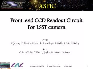
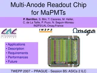
Implementation of two multi-channel ASICs for CCD readout. ASPIC (DSI design, LSST camera baseline) CLASSIC (Clamp & Sample design). ASICs designers : H. Lebbolo a , R. Sefri a , V. Tocut b

E N D
Implementation of two multi-channel ASICs for CCD readout ASPIC (DSI design, LSST camera baseline) CLASSIC (Clamp & Sample design) ASICs designers : H. Lebboloa , R. Sefria , V. Tocutb Tests & Characterization : Pierre Antilogusa, S. Baileya, P. Baillya, J. Jeglotb, C.Juramya,, D. Martina , M. Moniezb ,F. Wicekb a IN2P3/LPNHE , b IN2P3/LAL
The CCD are split in 16 segments of 1 M pixels : 2s readout time for the full focal plane => 500kHz LSST Focal Plane 189 Science CCD 4k X 4k 10mm pixels = 3 x109pixels for a focal plane of - 64 cm de diameter - 9.6 Deg 2 3X3 CCD “RAFT” Science Rafts (9 CCD): autonomous, fully testable 144 Mpixel camera. 1 Raft ~ 1/2 Megacam at CFHT LSST camera = 21 rafts Corner rafts : guidingand wavefront sensing ASICs for CCD readout
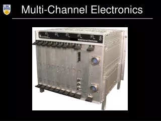
LSST camera readout system • 189 Science CCD x 16 outputs = 3024 readout channels • Request a compact readout chain inside the cryostat • The topic of this talk : ASIC for FE CCD readout ASICs for CCD readout
LSST Front End : ASIC for CCD readout specifications • Requirements : • CCD readout at 500 kHz (nominal) to 250 kHz • Noise : ~5nV / √Hz (or 7µV rms noise for 500ns integration ) • ( ~2 e- to be compared to 5 e- read noise for the whole CCD Chain) • Power dissipation at cryo temperature : 20-25 mW/channel • Crosstalk : 10-4 level ( 0.01% (goal) - 0.05% (max) ) • 90Keˉ Full Well capacity (150Keˉ max) • 0.5% linearity ( defined over 0 to 100 000 eˉ full well ) • Differential outputs • Output Load : 50pF // 1 k Ω • Power Supply 0/5V with respect to reference = 2.5 V • Running temperature 173K • Our initial worry : • Does a 8 channels ASIC will have the required low level crosstalk ASICs for CCD readout
Analog signal processing of CCD : DSI or C&S • The standard technique for analog signal processing of CCDs, is “Correlated Double Sampling”. It has been commonly implemented using one of the following schemes: • “Dual Slope Integrator” (DSI ) • “Clamp & Sample” (C&L) . • The first prototype implemented for LSST , the Analog Signal Processing ASic , (ASPIC I ), was a 8 channels ASIC with : • 4 DSI channels : The reference design for LSST is DSI. • 4 C&S channels : As we had a C&S design almost “ready” and considering the higher complexity of the DSI design and the R&D/unknown related to the crosstalk. ASICs for CCD readout
Analog signal processing of CCD : Dual Slope Integrator (DSI) Noise % 1/ sqrt (Tintegration) Clamp 1 gain , 2 integration constant time ASICs for CCD readout
Analog signal processing of CCD : Clamp and Sample (C&S) clamp Switch Noise % 1/ sqrt (Tau) With Tau = filter at the output of the C&S The “usage wants” Tau to be of the order 1/10 of the CCD signal width On ASPIC I , we had no filtering at the output of the C&S ( Tau ~ 35 ns ) ASICs for CCD readout
Analog signal processing of CCD :ASPIC I • Techno : CMOS 0.35µ 5V • Vendor : AMS • Package : CQFP100 4 DSI channels 3.8mm 4 C&L channels ASICs for CCD readout 2.7mm
Analog signal processing of CCD : ASPIC I Conclusion • The first prototype has demonstrated • DSI and C&S : implementation in a multi channel Integrated Circuit work at low temperature with low crosstalk • DSI : Good fit between measurements and simulations (based on an equivalent circuit using a linearized schematic to replace CDS switches) • C&S : gave competitive results • ASPIC II optimise Noise & Power and add functionalities DSI ASICs for CCD readout
Analog signal processing of CCD :ASPIC II • 3 input amplifier gains :2.5 – 5 – 7.5 • to deal with CCD gain spread. • 3 integration time constants : 500ns – 1µs – 1.5µs • to deal with CCD readout frequency. • Idle mode :DC current reduction by a factor of 1.000 baseline : { gain 5 + 500ns integration time} • Techno : CMOS 0.35µ 5V • Vendor : AMS • Package : CQFP100 • 8 DSI channels One ASPIC Channel ASICs for CCD readout
ASPIC II : Layout and improvement • LVDS inputs : 1.2V +/- 200mV terminated with 100 ohms • CDS clocks: clamp + integrator reset + signal integration + reference integration • CMOS inputs: 0V / +5V (compatible with 3.3V signals) • input gain and integration time select • Improvement compared to ASPIC I : • Noise: • 1/f noise reduced : amplifier first stage optimization • RC Input gain : noise source • Power consumption : • Source identified : amplifier output stage. ASICs for CCD readout
ASPIC II : Simulation Simulation Noise simulations of ASPIC 2 @ -100°C 6µV RMS noise for an Integration Time of 500ns ASPIC Proto2 Noise 0.1% Linearity -0.15% ASICs for CCD readout
ASPIC II : first results Simulation ASICs for CCD readout
“study on the side” : C&S version II ( CLASSIC ) • Pin to pin compatible with ASPIC 2 • 3 bit programmable gain input amplifier • 4 bit programmable output time constant filter to match the readout frequency (tau = 8ns to 392ns ) • Two differents C&S topologies (simulated noise ~ 1 e- for a power < 20 mW/channel and 500 kHz CCD readout) • Idle mode • Techno : CMOS 0.35µ 5V • Vendor : AMS • Package : CQFP100 • 8 C&S channels ASICs for CCD readout
Conclusion • We made a 8 channels ASICs with low crosstalk , low noise , low power, fast readout, for analog signal processing of CCD using CMOS 0.35µ 5V: • Such ASICs are needed for a large focal plane like the LSST one • If you are tired of fighting against « setup noise » , such ASIC with differential output directly in your cryostat could make your life so easier …. • If you were expecting a “3 sigma effect” between DSI and C&S (or C&S and DSI) …looks like it was the wrong talk … still the difference is always in the detail ( crosstalk vs time , ultimate readout speed, connection to CCD …) , and we are far to have completed the characterization of our second generation of prototypes . • For LSST, we now look forward to plug a LSST prototype CCD on our ASPIC II … ASICs for CCD readout