Download
1 / 50
500 likes | 522 Views
This strategic overview discusses the design elements, safety measures, and operational considerations of the bunker and its components in the context of the NSS project. Key topics include instrument systems, safety, radiation shielding, access, and integration of components.

E N D
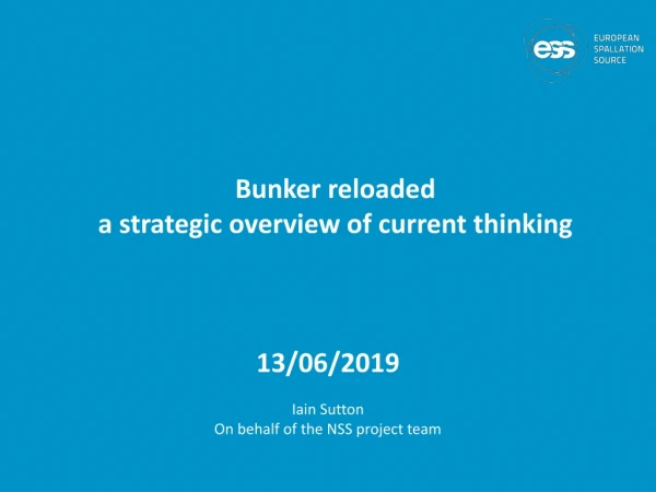
Bunker reloadeda strategic overview of current thinking 13/06/2019 Iain Sutton On behalf of the NSS project team
Approach conciousof the limits of the timeavailable …. • ratherthan present an overview i have chosen to try to second guess the issuesthatmay be ofinterest to you. • In principal i imaginethese to be the strategicissues and solutions potentialyrelevent to the design ofyourown systems
Game plan • overview instrument suite • overview bunker • bunker functions • volume for instrument components • safety • backgroundreduction • access • safety • radiologicalshielding • conventionalsafety • air activation / contamination • Backgroundreduction • Intergrationof instrument components • Operationalissues • access
The Bunkeran important operational ‘node’ Interdependencies Bi-directional Bunker is at once an ‘operational context’ and system within broader context … • NSS • Bunker system • Instrument systems • Target • NBPI • LSS / NBW • Facility • Crane • Utilities
Installed systemsInside / Outside / Feed through Target • 16 Beam extraction systems • 16 Light shutter • 42 Beam windows • Helium & Water cooling Instruments • Choppers 98 axis • Optics 300 m • Shutters 30 • Monitors 30 Service supplies • Vacuum 350m • Fluids 520m • Cables 5-10 km
ESS unique source,setting unique boundary conditions. 2 -3 times more mechanical devices on a ‘long pulse instrument’ than at existing types 60-70% of all ‘mechanical’ components on instruments are within bunker volume
Installed systemsInside / Outside / Feed through • Insert schematic of bunker components here BUNKER Perimeter In-monolith systems ‘Instrument systems’ Utilities Feed through
Overview Bunker context • Long • Short • Straight • Curved
Long pulse instrument • Like short pulse instruments only more so … • 3 times more choppers many in the first meters ie in bunker • Results in an elevated need for access for maintenance • Drive Bunker design
The bunker - content • Bunker (2) • Support frame • Shielding • Roof • Walls • Feed throughs • Neutrons • Utilities • Access • Safety Systems
Bunker SupportFrame R6m Frame Target building frame Instrument hall frame North and West sector • Design considerations: • Support bunker roof load of ~6.6 t/m2 • Support additional 3.3 t/m2 for removed roof block placement during maintenance • Prevent roof blocks impacting monolith during • an H4 seismic event • Provide minimal spatial constraints for beamlines & equipment • All elements to be removable as needed during maintenance
R6 Frame R6 frame assembly contains: • Wall Brackets • Connection Flanges • R6 beams • Support Pillars and Brackets • Skirt Shield Blocks The R6 beams will be fixed to the diagonal walls of the Monolith.
Wall West North-West North East South South-East
Wall North sector shown Every sector is build up from wall segments: Every wall segment is made of heavy concrete blocks:
Roof Level
Blocks installation – access cases The table presents illustrative access cases, as each one can be fully customized.
ESS-0060210, Bunker System, System RequirementsSpecification (SRS)
Unfolding the requirements Light Shutter Access is required for the following Target systems • Beam extraction (Insertion tool) • Light shutter • Beam-port window • ‘Target utilities’ Principal requirement(s) on bunker • Removable roof • Work area within volume free from permanent structures • Bunker support structure • Instrument components • Crane capacity Insertion tool Window utilities
Construction phaseTarget system Installation Target systems installed from monolith face / instrument hall • Light Shutter system • NB Optics (NBEX) • Beam-port window Target installations are primarily scheduled before bunker construction • Access • Free work area
Operational phaseTarget systems access Operation :Beam port activation Periodicity :yearly* IET : Remote handling tool & Cask for in-monolith plug • Mass 18+ tons • Length 5m Requirement fulfilled • Access • Free work area Roof removal Level of effort Blocks handled 23 Structural cross beams 1 Duration 12-16hrs
Conventional safetyFire ! Fire load Bunker Instrument systems • Cables ~16km • 100g plastic per m (1600kg combustible) • Borated plastic shielding ~3000kg • 20% plastic by weight (600kg combustible) Fire detection Yes Fire suppression Decision is still out but current design is expected to compatible with most fire suppression systems The real challenge will be to retain the maintainability of our systems
Conventional safetyHazards • Electrical • ODH • Access Physical division of space within bunker • @R11.5 • Long sector between beamlines
2 Feed through • Section is adequate for all instruments • Built in ‘halfen’ rails for attachment • Good access for installation • Vacant space to be filled with bagged shielding as required. • Steel shot • Borated poly New neutronics underway but no significant changes expected
3 Run Standard feed through Custom connection Standard section (4/2/1) Custom feeder Vertical Cable Chain Coupling • From feed through to POU it’s a Fixed installation • Route around access requirements • Exception for vacuum pipes (removable sections) Compact Support Rail
4 Point ofUsegoing the last mile • R7 > Chopper • Flexible / Snorkel • R12-R7 Feeder • Removable • Accessable • Q. Couplings R12 > Rigid R12 Quick Coupling
Which equipment should be equipped to be remote handled ? • Equipment which represents a significant hazard to personnel during interventions (due to activation). Eg >0.5mSv after 48hrs • PPS choppers • Shutters • Collimators 2. Equipment which requires regular intervention. • Overhaul or inspect period < 10 years. • Removed frequently i.e. is installed between R6 – R11.5 3. Equipment presenting a unacceptable risk of breakdown. Reliability < 98%
Zone I Remote handling Ready Solutions required for • Support structures • Fixations • Alignment & repeatability • Guidance in / out • Service connections Developed in collaboration with • More effort required • Vacuum vessel couplings
Unscheduled (breakdowns & unforseen) Activity Incidence over 10yr period • Beam-port systems breakdown 4 • Neutron chopper failure 40 • Optics breakdown 20 • Instrument shutter breakdown 20 • Other component breakdown 60 • Removal of hot components (neighboring work) 30 • Accident scenarios (H2) 2 NOTE : Indicative figures – work in progress
Operational Environment Zoning
Conditions in the Bunker (beam off)Component Activation Three contributions • Bunker shielding ESS 0416081 • Instrument components ESS 0087853 • Target systems In progress Target : hot spots <5 microSv/h@ 30cm Target Bulk shielding <2microSv/h (@30cm) Target value <15microSv/h (on contact)
Accessibility during shutdown- front of bunker Assumptions Gamma shutters present Aluminum guide housings Number of sources (>0.5) ~50 Source ‘density’ >3 per m2 Exposure regime ‘in-contact’ Delay for personnel access @Roof level ~ 48-72hr hotspot removal @Floor level > 7days Highly restricted (Hotspot removal) Tungsten Gamma source distribution 3days after shutdown (@contact)
Accessibility during shutdown- rear of bunker Assumptions Gamma shutters present Aluminum guide housings Number of sources 20-40 Source ‘density 0.5 per m2 Exposure regime ‘whole body @ 30cm’ Delay for personnel access @Roof level ~ 48hs hotspot removal or inspection @Floor level > 72hrs most areas with precaution* Tungsten Gamma source distribution 72hrs after shutdown (@contact)
Access strategyDivide and … protect R12 Access control fence Yellow >25 < 2500 microSv/h Restricted controlled Blue < 25 microSv/h Unrestricted controlled Entry point through roof - with access control Target for long periods <10 microSv/h Is this realistic ?
INTERVENTIONSIB - MINOR Inspection & Maintenance
‘Quick’ access- Short shutdown R6-R9 (Access ‘hole’) Number of blocks/lifts 9/18 Shielding mass 72t Handling time 4 – 6 hr R6-R11.5 Number of blocks/lifts 23/46 Shielding mass 190t Handling time 10-12hr
Access Short shutdown Short shutdown 3-5d • Default mode of access • From above • Remote N
Access Short shutdown rear II • Exceptional work mode • Access from above • Hot spot mitigation • Floor • Probably not feasible once operating at moderate or high power N
Design constraints - all systems Principal constraints Bunker • Modular roof • Removable roof beams • Frame stability • Materials (activation) Utilities • Utilities routed around or removable Instruments • Vertical extraction • Restricted Materials (activation) • RH compatible Target • Materials (activation
Utilities routing USE 4 • Iain slide USE 3 USE 2 ENTRY 1 • Scope • Within shielding ‘bunker’ from Point of entry to Point of use • Bunker entry • Technical feed through • Run • Point of use connection
INTERVENTIONSI A - MAJOR Installation & Overhaul
InterventionsIA Major Type of activities • Installation / Overhaul • Duration: weeks > months Principal activities Periodicity Instrument • Upgrade 10yr • Installation/Replacement 15yrs Target • Beamport activation 10yr • NBEX renewal 15yr Operations per year 1,5-3
Access Long shutdown / Part I Cool down period • Cool down 3-5 days • Shielding removal 2 days • Hot spot removal • Local shielding placement Shielding removal Hot spot mitigation N
Access Long shutdown Floor level Access N
‘Full access’ Long instrument- long shutdown R6-R28 Number of blocks/lifts 52/104 Shielding mass 750t Handling time 24-30 hrs Frame beam removed ~11
Intervention MajorDesign constraints - all systems Principal constraints Bunker • Modular roof • Removable roof beams • Frame Stability Utilities • Utilities routed around or removable Instruments • Vertical extraction • Restricted Materials • RH compatible
Logistics 2,3m 3,6m free height 6,7m from TCS 1,3m 3,1m 1.8m N Principal requirement Free height below hook > 3m
LogisticsImplicit requirement on cranes (& instruments) Experimental Hall crane coverage area Cranes crossover (load interchange) area Monolith crane coverage area
Crane route Bunker crane Exchange zone Storage zone Hall crane
NBEX locations and transport IET transport ACF docking IET handover on bunker roof from bunker crane to D01/D03 crane Exchange route NBPI/NBPP Vertical handling test stand Horizontal handling test stand LSC transport