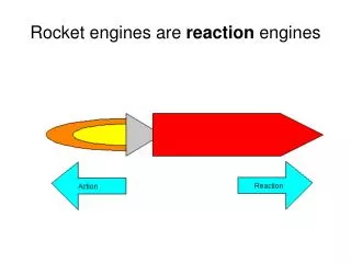
Hybrid Rocket Engines
Hybrid Rocket Engines. Note on Temperature Effects in Solid Rocket Motors. where . is change in temperature from the “standard” value where a and n are measured. Define. where T is the propellant grain temperature before combustion. .

Hybrid Rocket Engines
E N D
Presentation Transcript
Note on Temperature Effects in Solid Rocket Motors where is change in temperature from the “standard” value where a and n are measured. Define where T is the propellant grain temperature before combustion. It can be shown that for a propellant obeying St. Robert’s Law, Values: 0.06% < < 0.18% per Kelvin 0.16% < < 0.30% per Kelvin
Erosive Burning Effects In Solid Rocket Motors Combustion due to increased heat flux from high speed flow at the end of a long propellant grain. Correlation by Lenoir and Robillard: where and b are empirical constants; L is the grain length G is bore mass flux The 0.8 exponent is from effects of convective heat transfer Design guidance: increase the bore at the aft end in the early stages of motor operation.
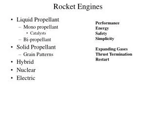
Hybrid Rocket Motors Hybrid Rocket Motors “Hybrid Rockets” combine one liquid propellant with one solid propellant – typically a solid fuel and a liquid oxidizer. www.ukrocketman.com/rocketry/ hybridscience.shtml • Oxidizers • LOX • H2O2 • N2O4 • LF2 (Can be combined with LOX)
Hybrid Rocket Motors www.propulsionpolymers.com/ images/MarcusBill.jpg
Hybrid Rockets Safer than liquids and pre-mixed solids (easy handling) Can be throttled, shut down Isp is between solids and liquids (300-320 sec) Bulk density is good (better than liquid, but not quite as good as a solid) Exhaust need not be toxic Not as sensitive to exposed cracks as solids Low regression rate (needs more port area to generate required thrust) Burn is often incomplete due to complex port design
Hybrid Rocket Motors Fuels HTBP: Hydroxy-terminated polybutadiene: rubbery HC binder from solid fuels. Plexiglass (Polymethyl-methacrylate PMM) (Early: coal, wood, rubber) In some cases carbon black or aluminum powder can be added to the fuel grain to increase burning
Burn rate and Regression rate There are several burn rate models, but a good one is: G = total mass flux (kg/(m2s)fuel+oxidizer) X = distance down the port (m) a = regression coefficient In theory, However, experimentally
Note: This equation uses where both are a function of so the implicit solution is iterative to determine
Burn rate depends on flow rate and downstream distance Here, the key observations are, • r is proportional to G(x) (and thus G) (can be turned off) • burn rate decreases with length along L. • This is primarily due to the diffusion nature of the flame region. • As the boundary layer grows, flame moves away from surface; heating rate decreases. As a result, the regression is slightly longer at the injector end
Other Empirical Fits For Burn Rate Other burning rate equations exist and may be better in some cases; e.g., (averaged method) average regression rate average oxidizer flux port length This equation is simpler in that it depends on average values. May be ok for performance predictions. Table 7.5 in Humble – curve fits to AMROC data for various equations.
Change in O/F Ratio As the solid fuel is burned (web is consumed) the port area increases and thus Gox decreases . As such, decreases and will increase over time. This causes a shift in and as the motor burns. Over a given O/F range the Isp might shift by a few %.
Typical Port Configurations In general, two ports will have the same oxidizer flow rates if their hydraulic diameters are equal. Hydraulic diameter is defined as 4*(cross-section area)/(wetted perimeter). Objective: maximize volumetric efficiency, minimize sliver fraction, keep (thus Gox) the same in all ports. Fig. 7.17&18 from Humble shows typical port configurations for hybrid rockets, and the associated variations of volumetric efficiency and chamber length-to-diameter ratio (L/D) as a function of required fuel mass. • Circular : Low and large size. • 7-cylinder cluster : high sliver fraction (residuals) • Wagon Wheel with center port: good compromise at larger size Note: The wagon wheel design is more difficult to solve analytically, but can be solved numerically.
Port Configuration Using multiple ports (holes) on a hybrid system will allow us to have more surface area exposed to the oxidizer and thus generate more thrust for a given diameter. Define Volumetric efficiency “Skew Fraction” = (1- mass of solid fuel used) / (mass of solid fuel available)
Note: for a circular port, hydraulic diameter is the actual diameter =D
Performance Analysis For a given propellant with: m/s regression rate and a given grain geometry N ports For a given , find Aport alternate versions of this are available (e.g., but require iteration) Dimensions known: Dn and L given N= number of ports
For a given , find alternate versions of this are available (e.g., but require iteration) N = number of ports SP = surface area of a single port Dimensions known: Dn and L given
Time-stepping procedure is find from charts in Appendix B of Humble Since
find CF and thus thrust and Isp (Note: throat erosion can cause to change over time) Given For a small time step, hold constant and use to find new port cross section area ( ) and surface area Repeat until first web segment is nearly consumed or tb is reached.
Example calculation from pp 433-434 in Humble Isp vs. time from table Thrust vs. time from chart (7 port Wagon Wheel, no burning in center port)
Hybrid Motor Ballistics This derivation is from the text by Humble. It is presented to illustrate the basis for the empirical expressions for burn rate. Equation numbers are the same as those in Humble et al. The burn rate of a solid fuel in a hybrid rocket motor also depends on oxidizer flow rate. Thus fuel regression rate is Here, is expressed in m/s. Note that its values are typically in mm/s or cm/s. G= total propellant in Kg/m2s X= distance down the point a, n, m are regression rate constants of the propellant.
is a function is also G increases with x. A major difference from solid and liquid rockets: hybrids burn in a diffusion flame, as opposed to the premixed flames in the other types of rockets. In solid rockets, O/F is independent of x. However, in hybrids the O/F ratio does vary with x.
Interior Ballistics Model • Turbulent diffusion flame • Controlling factors: • rate of heat transfer to surface. • heat of decomposition of solid fuel. • G determines rate of heat generation and hence flow • The flame occurs within the turbulent boundary layer. Note that the axial velocity (i.e., the velocity component directed along the axis of the port) at the flame zone is thus lower than the velocity at the edge of the boundary layer.
Note: Non-dimensional parameters (source: Hill & Peterson) Nusselt number (for convective heat transfer): Stanton # Heat transfer Film coefficient: is such that . From this, we can see that and
The burning rate equation is: heat flux transferred from flame to solid surface mass flux rate of vaporized fuel, perpendicular to surface heat content of unit mass of gasified fuel at surface minus heat content of solid at ambient temperature (J/Kg ) • includes: • heat to warm solid to surface temperature • thermal changes such as depolymerization • heat of vaporization measured in labs.
Heat transfer through boundary layer occurs by conduction, which is proportional to the thermal gradient. k: molecular/turbulent boundary layer gas conductivity (J/msk) T: gas temperature at any point y(x) h: Specific enthalpy of gas at any point y (J/kg) Specific heat of gas at constant pressure (J/kg) The form in terms of the enthalpy gradient: is useful when chemical recombination occurs in the boundary layer.
In terms of the Stanton # …….. (7.4) axial mass flux in flame zone Total specific enthalpy difference between flame and wall (J/kg) gas density at flame Gas velocity at gas flame (m/s)
CH can be determined from friction coefficient CF for which experimental data are available for turbulent flow over flat plate. Assume: • Prandtl # = 1 = • Lewis # = 1 (diffusivity of heat and molecular species are equal) Reynolds analogy: temperature/enthalpy profile through a boundary layer is proportional to
Using Reynolds analogy, shear stress at y (Pascals) U: axial velocity at y
Integrating equation 7.5 between the burning zone and the surface, Divide by Compare with 7.4:
From definition of where = freestream gas density (kg/m2) = freestream m/s = flow friction coefficient
From (7.8) For non-combusting boundary layer,
Here, boundary layer is extended due to “blowing” from the surface due to fuel vaporizing. Expecting blowing to have similar effects on heat and momentum transfer Combine 7.2, 7.4, 7.12, 7.13: Basic expression for burning rate in hybrid rocket: Evaluate skin friction coefficient from empirical law for turbulent boundary layers. Empirical law for is C: 0.3 (empirical) =
With equation 7.15 for mass flux rate of fuel from solid surface (kg/m2s) = regression rate (m/s) of solid fuel. = density of solid fuel viscosity of burned gas Stanton # with blowing Stanton # without blowing
Combine Eqns. (2) (4), (10) (determined from propellant properties.) Maxman 1964:
Combustion instability in hybrids Hybrid rockets often exhibit combustion instability (pressure oscillations) during burning derived from 1.oxidizer feed pressure oscillations (Chugging) 2. flame holding instability (acoustic) Increasing the injection velocity and reducing sources of compressibility in the feed system will address the former (#1). Preheating the oxidizer either with a hydrogen or propane pilot flame or by creating a re-circulation zone at the head-end of the motor will improve the latter (#2) (Fig. 15-13 Sutton)