Magnetic External Pre-Isolator
This document details the historical installation and performance overview of the Magnetic External Pre-Isolator (MEPI) system, addressing challenges in plant modal control, actuator housing improvements, and the effectiveness of various plant modifications. We discuss control strategies, including the performance of constrained layer damping and stiffening beams, and examine the system's response to magnetic interactions. Future directions aim at refining controllers, enhancing sensor corrections, and characterizing low-frequency performance to optimize isolation.

Magnetic External Pre-Isolator
E N D
Presentation Transcript
Magnetic External Pre-Isolator Richard Mittleman, David Ottaway & Gregg Harry April 18, 2003
Historical Overview • SISO Controller • - We could not simultaneously close 3 horizontal or 3 • vertical loops 2) True Modal Controller (Use the modes of the plant) - Not Very Stable, i.e. small plant modifications made substantial changes to the modal structure - The Modal decomposition was very time consuming - The resulting modes did not have the intuitively expected symmetries. - The HAM plant is not very stiff above 15Hz. - The resulting transfer functions were not any simpler then a Cartesian decomposition (i.e. X, Y, Z . . .). 3) Plant Modifications (T030073-1) - Stiffened the plant in the X-direction by adding the stiffening beam. - Added constrained layer damping on the gull wing support to reduce the high frequency modes
Plant Modifications Constrained Layer Damping Stiffening Beam
Plant Modifications Results The constrained layer damping did not have much of an affect (Probably) The stiffening beams changed the transfer functions substantially
More Modifications 3) Plant Modifications - Since the control design and performance measurements the actuator housing attachment to the piers has been improved - The 51Hz mode in the Y-mode, which corresponds to a vertical flexing of the stiffening beams, will be damped using either a piezoelectric damper (Jonathon Allen) or a tuned mass damper (Lei Zuo). 4) Now in Cartesian Coordinates - Current demonstrated control has 7 controlled degrees of freedom, notation left over from Modal decomposition X, Y, Z Phi = Rotation about the Z axis Alpha = Rotation about the X axis Beta = Rotation about the Y axis Vertical Pringle
Control Strategy (Streckeisen STS-2)
Blending We did not try to do any shaping with the blending filters. The horizontal-tilt coupling sometimes made the blending challenging
Control We have added some resonant gain stages
More Control We have used some plant inversion
Even More Control There is some coupling between modes (See 32Hz resonance)
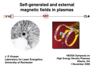
Magnetic Interactions • Tests indicate no magnetic interaction with geophones • Magnetic field from actuator above background from DC to 300 Hz • Possible added IFO noise from magnetic interaction with test masses (see figure) • Measurements at sites saw no effect from from actuator field • A box around each actuator with walls 2.5 mm steel and mu-metal layer eliminates any problems Noise in m/Hz1/2 vs. frequency in Hz showing SRD noise (dotted) and predicted noise from MEPI (solid) Full write up (including heating of actuators) in T030072-00-R
Performance This is a ratio of the transfer functions from the Streckheisen siesmometer on the floor to the L4C geophones on the optical table. TF(Piers Free) TF(Piers Locked) The sensitivity is limited at low frequencies (<0.5Hz) by the 1Hz geophones and at high frequencies (>10Hz) by the isolation of the stack.
More Performance This is a ratio of the transfer functions from the Streckheisen siesmometer on the floor to the L4C geophones on the optical table. TF(Under Control) TF(Piers Locked) It should be noted that since we only have 3 geophones on the optical table that these sensors are sensitive to more than one mode.
Latest Results (X-Mode) The ratio of the power spectra with the controls on/controls off
Latest Results (Phi-Mode) The ratio of the power spectra with the controls on/controls off
Latest Results (Y-Mode) The ratio of the power spectra with the controls on/controls off
The Future • Improve Controllers • - The demonstrated system performance was based on 7 loops • - Insert Horizontal Pringle Loop (#8), if it looks like it will help. • - Add/Improve resonant gain • - Other control schemes are being considered (SISO/MIMO combination) • 2) Take Advantage of Plant Modifications • - The improved actuator to pier coupling has reduced or eliminated some of the high frequency modes. • - Damping the 51Hz mode should allow a better Y and Alpha mode controller. • 3) Improve the Sensor Correction • - The sensor correction has only been measured very crudely (~10%) and is almost certainly limiting the isolation. • 4) Characterize the Low Frequency Performance • - The 1 Hertz L4C Geophones are not the correct instrument to us in the 10-100 mill Hertz range. We are currently installing a STS-2 on the support table and will (CAREFULLY) use it to access the low frequency system performance.