Download
1 / 35
360 likes | 605 Views
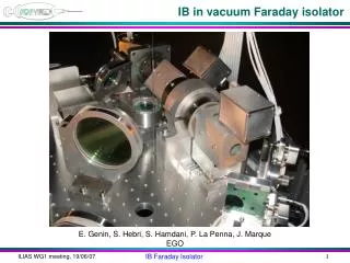
IB in vacuum Faraday isolator. E. Genin, S. Hebri, S. Hamdani, P. La Penna, J. Marque EGO. IB Faraday isolator in vacuum.

E N D
IB in vacuum Faraday isolator E. Genin, S. Hebri, S. Hamdani, P. La Penna, J. Marque EGO IB Faraday Isolator
IB Faraday isolator in vacuum • Why a Faraday isolator between the IMC and the PR: the ITF reflected light (with PR aligned) induced noise in the IMC (converted in frequency noise): impossible to lock the recycling cavity at full power • Beam out of IMC: 5 mm waist: need of a large Faraday isolator • Two candidates: EOTech (larger aperture) and Isowave (lower absorption) • The Faraday isolator: • Electro Optics Technology (EOTech), with 20 mm aperture, vacuum compatible: • Crystal: TGG (1.8 mm length), • ~1 T magnetic field • two Brewster thin film polarizers (Karl Lambrecht) • about 20 cm long • 3.5 kg weight • 10,000 $ cost • The Faraday isolator had been tested in Nice with 20W Yag beam in air: more than 40 db isolation (factor 10,000 in power), no significant thermal lensing effect • After the new IB installation, with the Faraday, it was possible to lock soon the recycling cavity with full power IB Faraday Isolator
Brewster dielectric polarizers Rotator February 2005 IB Faraday Isolator
20W Pump Faraday 2f 2f Shack- Hartman HeNe (F.Cleva) IB Faraday Isolator
20 W Nd:YAG input power: • Two rods: • Rod 1, • Beam waist 1.1 mm: focal length = 31 m • Rod 1, Beam waist 2 mm : focal lenght = 90 m Fth~ 1/w2 • Rod 2, Beam waist 2 mm : focal length = 82 m First rod less absorbing than second one • Optical isolation: larger than 42 dB (less than 0.008 W backreflected) IB Faraday Isolator
Where is the IB Faraday IB Faraday Isolator
Two main problems experienced: • Change of isolation from air to vacuum • Thermal lensing: • Change of beam shape and beam/ITF matching IB Faraday Isolator
Faraday isolation measurement SIB Faraday Power reflected measured on the Laser Bench (rejected by the last Laser Bench Faraday). LB Faraday Power meter IB Faraday Isolator
Isolation was less than 100 In order to optimize the attenuation (40 dB) the first polarizer had to be rotated by about 5 degrees: Cleary some problem there Input light (7 W) IB Faraday Isolator
Explanation • This could be explained by a change in the magnetic field (by 10 mT, total field about 1 T) • Explanation: the internal magnetic field was perturbed by the presence of an Allen key inside • After removal the first polarizer was turned back, isolation on Laser Bench (in air) was better than 40 dB, second polarizer reflection of the order of 100 mW IB Faraday Isolator
Explanation IB Faraday Isolator
Isolation tuning • After Allen key removal the polarizer could be turned back close to the nominal position (defined by a marker) • In this condition we tuned the isolation: measured on the laser bench it was more than 10,000 • We blocked the Faraday and realigned optics and mounts in this condition • Then the IB tower was closed, evacuated, and things changed: the isolation dropped to less than 1,000 IB Faraday Isolator
Isolation: before (WS1) and after (WS2) Purple: WS1 Black: WS2 IB Faraday Isolator
Isolation improvement 0.75 0.05 Black: WS1 (before improvement) Purple: WS2 (after improvement) More than factor 10 improvement (factor 15) IB Faraday Isolator
Absolute power measurement (power meter) 1V = 30 mW 12 mW Isolation: 9.5 W /12 mW > 800 (it was 10,000 in air: more than factor 10 lost) IB Faraday Isolator
Isolation improved by more than a factor 10 (but 800 now) • No explanation why it is not 10,000, as measured with the IB tower open: • Different alignment? • Temperature? • Remote tuning necessary? IB Faraday Isolator
Finite elements Matlab model radiation conduction Shield or not Vacuum or not heat radiation air cooling air cooling M. Punturo Matlab’s algorithm Gaussian beam IB Faraday Isolator
Tuned in air at 40 dB: changes in vacuum • Thermal dependance of Verdet constant: Expected change of isolation from air (40 dB) to vacuum, depending on TGG rod absorption IB Faraday Isolator
LIGO measurements: isolation changes in vacuum (A. Lucianetti, LIGO) IB Faraday Isolator
Tuning of Faraday isolation L/2 Crystal: about 43.7° rotation IB Faraday Isolator
Tuning of the Faraday isolation Crossed polariz.comp. reflected away L/2 Crystal: about 43.7° rotation 2nd polarizer (with respect to first pol.): about 45° + (45°-43.7°) rotated IB Faraday Isolator
Tuning of the Faraday isolation 2.6° rejection L/2 43.7° 0° 45+1.3° 45+1.3°+0° 45+1.3°+43.7° Total rotation: 45°+1.3°+ 43.7° = 90° : good isolation (P2 reflects light) IB Faraday Isolator
If crystal rotation changes L/2 45°+1.3° 43° 43° 0° Total rotation: 45°+1.3°+43° = 89.3° : worse isolation IB Faraday Isolator
Compensation Larger rejection: 4° L/2 L/2 -0.7° 45°+1.3° 43°-0.7° 45°+1.3°+43 45°+1.3°+0° Total rotation: 43°+45°+1.3°+0.7° = 90° : good isolation IB Faraday Isolator
motorized waveplate IB Faraday Isolator
Two main problems experienced: • Change of isolation from air to vacuum • Thermal lensing: • Change of beam shape and beam/ITF matching IB Faraday Isolator
RFC matching improvement after PR alignment PR alignment RFC ref RFC trans IB Faraday Isolator
Changes in shape with PR alignment B1p camera beam shape PR_ty 1500 mrad misaligned PR_ty -150 mrad misaligned IB Faraday Isolator
Beam/ITF matching: free swinging cavity TEM0 Amplitudes of SB is 3% modulation index = 0.3 TEM0 TEM1+usb lsb TEM2 TEM3 TEM5 TEM4 TEMX means sum of TEMnm with n+m=X TEM2 is 2.5% of TEM0 (J.Marque, November 2006) IB Faraday Isolator
Matching change with PR alignment When the PR is misaligned by 150 mrad there is more light passing through the Faraday isolator (larger heating) • Matching depends on the alignement of PR mirror: • 3-4% when PR is misaligned by 150 µrad with respect to PR misaligned by more than 1mrad. • After power reduction (20%) the difference in mismatching became: • 2.5% : PR misaligned 10 mrad • 3.5% : PR misaligned 150 mrad IB Faraday Isolator
Expected vs measured matching change • Expected focal length with 10+10 W (PR aligned): 160 m, 1% mismatching • Measured with • PR aligned: 3.5% • PR misaligned: 2.5% 3.5%: PR aligned 2.5%: PR misaligned 1%: expected with 160 m Fth (20 W, 2.65 mm waist, obtained with good telescope alignment) 360 m Fth: 10 W, 2.65 mm waist IB Faraday Isolator
fit limits ~+- 1waist (S. Hamdani) Matlab + Zemax Circle fit Radius of curvature focal Zemax IB Faraday Isolator
Thermal lensing: Virgo vs Virgo+ vs AdvVirgo • Virgo: • 10W + 3W • mismaching:~0.5% • Virgo +: • 40W + 10W • mismaching:~5% • Advanced Virgo: • 150W + 50W • mismaching:~37% VIRGO+ (50Watt) Thermal lens: f=66m Mismatch: 5% Advanced VIRGO (200Watt) Thermal lens: f=13m Mismatch: 37% (E. Genin, S. Hamdani) IB Faraday Isolator
Thermal induced focal length: compensation DKDP Compensator IB Faraday Isolator